


i
n
q
u
e
s
t
o
m
o
n
d
o
,
f
o
r
s
e
,
u
n
o
s
i
d
i
c
e
s
e
d
i
c
i
a
m
o
c
h
e
m
a
s
c
r
i
v
e
n
d
o
c
o
n
i
n
q
u
e
s
t
o
m
o
n
d
o
,
f
o
r
s
e
,
u
n
o
s
i
d
i
c
e
s
e
d
i
c
i
a
m
o
c
h
e
m
a
s
c
r
i
v
e
n
d
o
c
o
n
m
a
s
c
r
i
v
e
n
d
o
c
o
n
i
n
q
u
e
s
t
o
m
o
n
d
o
,
f
o
r
s
e
,
u
n
o
s
i
d
i
c
e
s
e
d
i
c
i
a
m
o
c
h
e
m
a
s
c
r
i
v
e
n
d
o
c
o
n
m
a
s
c
r
i
v
e
n
d
o
c
o
n
i
n
q
u
e
s
t
o
m
o
n
d
o
,
f
o
r
s
e
,
u
n
o
s
i
d
i
c
e
s
e
d
i
c
i
a
m
o
c
h
e
m
a
s
c
r
i
v
e
n
d
o
c
o
n
s
e
d
i
c
i
a
m
o
c
h
e
m
a
s
c
r
i
v
e
n
d
o
c
o
n
4–2
FM1000A User’s Manual
Introduction
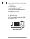
The FM1000A is a solid state RF amplifier package designed to deliver 500 to 1000
watts. The package consists of two separate, compact units—a power supply
(PS1000) and a power amplifier (PA1000). In turn, these units consist of modular
components which provide for efficient operation as well as ease-of-service.
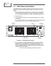
4.1 PA1000 Power Amplifier
The PA1000 power amplifier features adjustable output to deliver 500–1000 watts of
RF output power for broadcast transmission. The amplifier is broadband; no tuning
is required. The design, however, ensures efficient operation. Typical RF efficiency
is 75% to 85% across the FM band.
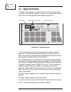
4.1.1 Power Modules
The primary components of the PA1000 are two, 500–watt power modules. These
power modules are mounted by stacking two in the right cavity of the chassis. The
two slots on the left side are unpopulated.
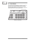
The chassis of the power modules acts as a heat sink for the MOSFET amplifiers.
There are two power amplifiers mounted to spacer plates on each of the heat sinks,
for a total of four power amplifiers in all. (The power amplifiers are the same as
those utilized in the Crown Broadcast 100, 250, and 500–watt transmitters.)
Power from the amplifiers is combined through a micro-strip combiner to convert
from 50 Ω output impedance for each amplifier to an intermediate impedance and
then return to the 50 Ω output at the Low Pass Filter. This technology eliminates
tuning and adjustments throughout the 88–108 FM band and enables each amplifier
to equally share the power load. The power combiner is also designed to allow a
module to be disconnected from the combiner and removed without adversely
affecting the impedance balance of the unit. With one module removed the imped-
ance change allows the remaining module to continue operation at approximately
one-third of the full output power.
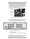
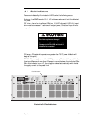
4.1.2 Power Combiner Board
There are two Power Combiner Boards; one attached to each of the two heatsinks
overlapping the amplifiers. Each board takes the power from two amplifiers and
combines it through a parallel quarter-wave transmission line transformer network.
The power is then summed in a common point junction on the Output Combiner
Board.