


page 7
CH and CL Series Power Amplifiers
Operation Manual
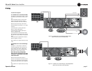
2.4 Choose Input Wire
and Connectors
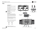
You have three choices of input connectors: 1/4-inch (6.35-mm)
phone, 3-pin XLR, or barrier strip. You can also use either bal-
anced or unbalanced wiring.
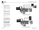
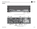
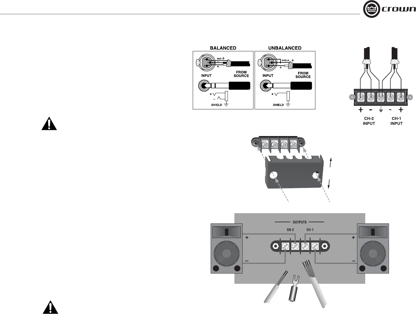
Figure 2.3 shows balanced connector pin assignments for XLR
and phone. Figure 2.4 shows unbalanced connector pin assign-
ments for XLR and phone.
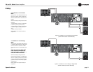
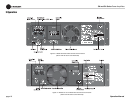
Figure 2.5 shows barrier strip input wiring for a balanced signal.
Both channels should be wired using a common center terminal
for ground connection.
NOTE: Custom wiring should only be performed by
qualified personnel.
Figure 2.3 Balanced
Input Connector
Wiring
Figure 2.4 Unbalanced
Input Connector
Wiring
2 Setup
2.5 Choose Output Wire
and Connectors
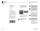
Crown recommends using professionally constructed, high-
quality, two- or four-conductor, heavy gauge speaker wire and
connectors. You may use terminal forks or bare wire for your out-
put connectors (see Figure 2.7). CH and CL Series amplifier ter-
minal strips accept up to 10 AWG terminal forks which fit over a
#8 screw.
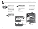
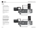
To prevent the possibility of short circuits, wrap or otherwise
insulate exposed loudspeaker cable and connectors. Also, a no-
touch cover, which covers the terminal strips, is provided to help
prevent short circuits. To remove this cover,
1. Loosen screws inside top and bottom holes of cover (see Fig-
ure 2.6).
2. Slide cover up or down, then pull it off away from the amplifier.
Using the guidelines below, select the appropriate size of wire
based on the distance from amplifier to speaker.
3. Reinstall no-touch cover to maintain safety.
CAUTION: Never use shielded cable for output wiring.
Distance Wire Size
up to 25 ft. 16 AWG
26-40 ft. 14 AWG
41-60 ft. 12 AWG
Over 60 ft. 10 AWG
Figure 2.7 CL Series and CH4 Output Connector Wiring
Figure 2.5 Barrier Strip Input Wiring:
Balanced Signal In
2. SLIDE then
PULL OFF
1. LOOSEN
SCREWS
Figure 2.6 How to
Remove the No-Touch
Cover