


Operation Manual
CH and CL Series Power Amplifiers
page 26
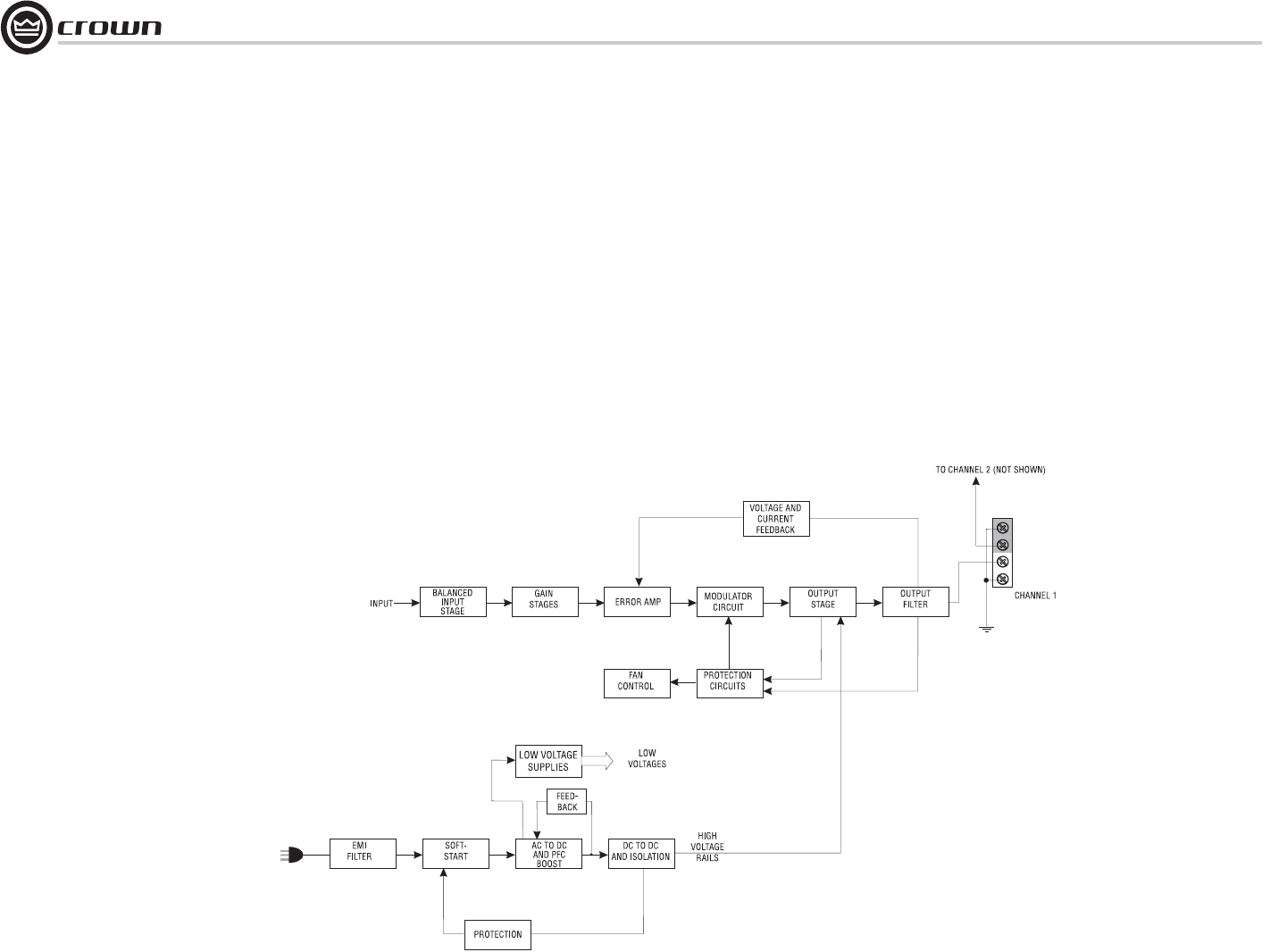
The signal next enters the main amplifier error
amp where it is mixed with a small portion of
the output voltage and current in such a way as
to control the amplifier’s overall output perfor-
mance.
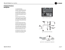
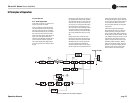
Following the error amp is the modulator stage
where the audio signal is compared to an
extremely accurate 250-kHz triangle waveform.
Comparators output a Pulse Width Modulated
(PWM) string of pulses at 250 kHz that vary in
width depending on the level of the input sig-
nal. These strings of pulses, one for the posi-
tive side and one for the negative side, are
connected to the output stage via optocouplers.
The signals from the optos are then passed to
gate drivers that amplify the pulses to the level
required to drive output devices. The driven
output devices are now able to produce PWM
pulses that have an output voltage from the
negative high-voltage rail (–Vcc) to the positive
high-voltage rail (+Vcc). This output voltage is
always the same (2 * Vcc) but the width of the
pulses is still dependent on the level of the
input signal. The positive and negative output
PWM pulses then pass through inductors and
are summed together. Summing the output sig-
nals through inductors reconstructs the audio
signal, amplified to the desired level. There is a
small amount of ripple on the output that is at
double the switching frequency (500 kHz).
The amplified audio signal is then passed
through an output filter that removes the resid-
ual ripple voltage.
Protection for the output devices is performed
by a very precise pulse-by-pulse current limiter
circuit that operates each time the output
devices switch. The current limiting is “flat”
meaning that, regardless of the output voltage,
the output current always limits at a certain
value.
The turn-on delay circuitry functions to keep
the modulators turned off (which keeps the out-
puts from switching) until all supplies are up
and stable.
Thermal probes monitor Heatsink tempera-
tures and power transformer temperature. As
the temperatures rise, the probes send a pro-
portional voltage to the fan control circuit and
the Thermal Limit Control (TLC) circuit. The fan
5 Principles of Operation
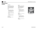
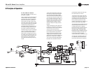
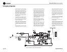
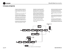
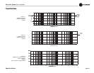
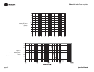
Figure 5.4 Model CL4 Circuit Block Diagram