


Commercial Audio Series Mixer-Amplifiers
page 7
Operation Manual
1 Welcome
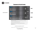
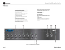
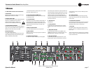
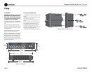
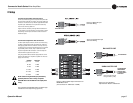
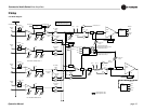
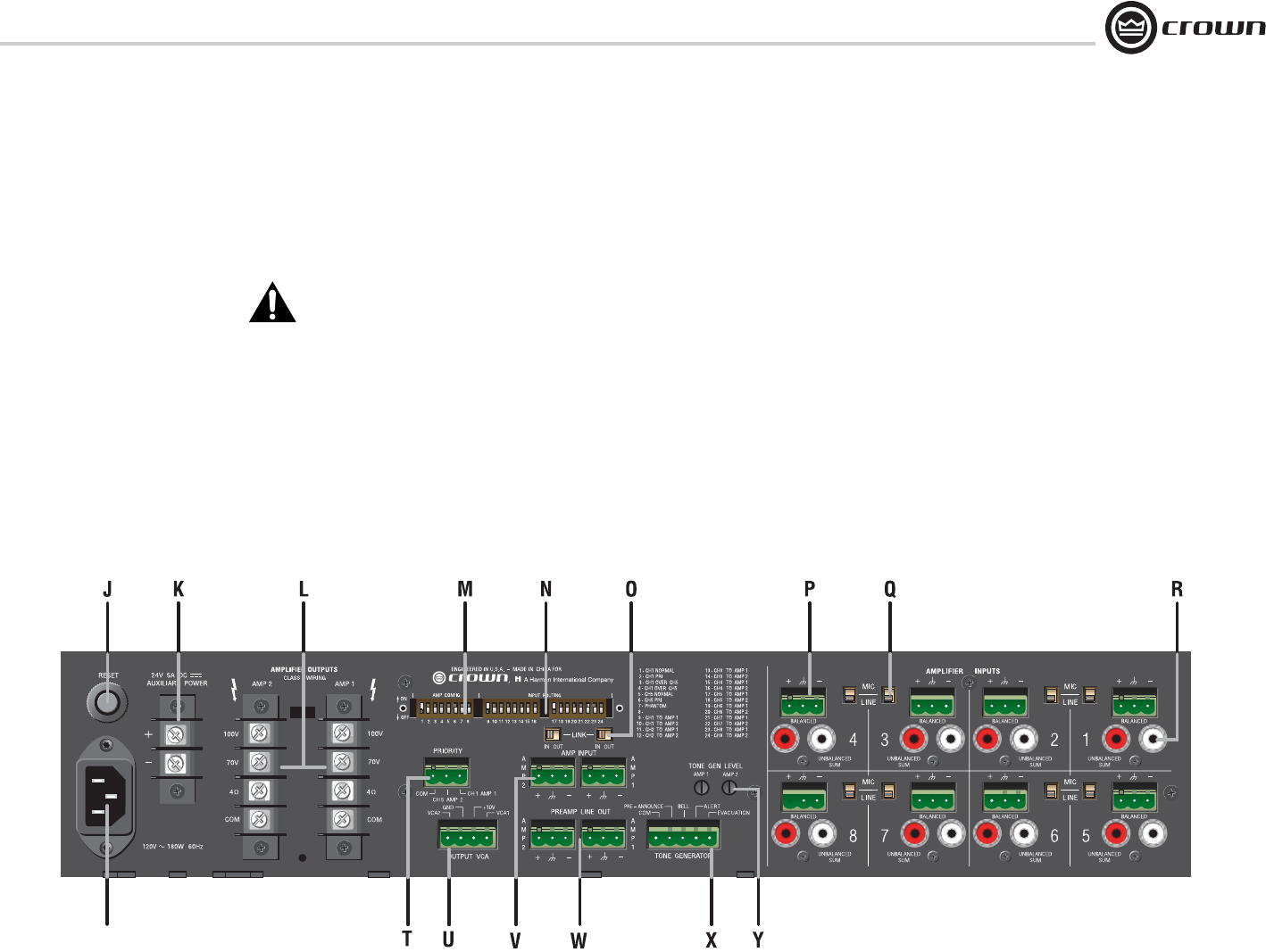
Figure 1.2 Back Panel Controls and Connectors
(280MA shown)
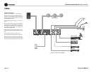
2. Global enable switch for phantom power. Does not affect
RCA inputs. Default position is off.
N. Input Routing Switch (280MA only)
DIP switches that assign each input signal to each output.
Two switches per input.
O. Link In/Out Switch
Slide switch, one per channel. With the Link Switch IN, any
signal applied to the Amp Input connector will be mixed
with the input signal(s). With the Link Switch OUT, only the
signal from the Amp Input Connector will appear at the
amplifier output.
P. Mic/Line Input Connector
3-pin Phoenix-type, balanced, one per input channel.
Q. Mic/line Switch
Selects mic-level or line-level input signals. One switch for
each balanced input.
R. Dual RCA Input Connector
For stereo music signals, unbalanced, summed together,
two connectors per input channel. If required, both the mic/
line and RCA inputs may be used at the same time. The mic/
line gain switch does not affect the RCA gain, which is fixed
relative to mic/line. The mic/line and RCA signals are
mixed. Note: Other equipment connected to the RCA jacks
should be connected to the same AC power source as the
mixer-amp to avoid hum.
S. AC Power Inlet
Detachable IEC.
T. Priority Connector
3-pin Phoenix-type connector allows Input 1 or Input 5
(280MA only) to mute other input signals by contact clo-
sure.
U. Output VCA Connector
4-pin Phoenix-type connector for one (180MA) or two
(280MA) VCA control lines of +10 VDC and ground. Com-
patible with Crown 1-VCAP and 4-VCAP modules.
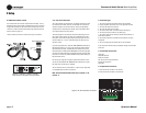
V. Amp Input Connector
3-pin Phoenix-type, high-impedance balanced, one per
amplifier channel. Used to link an additional mixer to the
mixer-amplifier. Or used to connect an external processor
(see Section 2.9).
W. Line Out Connector
One 3-pin balanced Phoenix-type connector per output
channel. Post master, pre-VCA. Level controlled by master
volume control.
X. Tone Generator Connector
5-pin Phoenix-type connector. Tones include Pre-Announce
Chime, Bell, Alert Tone, and Evacuate Tone. All tones are
activated by contact closures on the connector.
Y. Tone Level
One potentiometer per output channel sets the volume of
the tones. Tone level is not affected by output volume con-
trols or VCAs.
The Pre-Announce Chime is a special case. It is mixed with
Channel-1 signals, so its level will be affected by the master
volume control and VCAs.
1.3 Back Panel Controls and Connectors
J. Reset Switch
Resets the circuit breaker that protects the power supply.
220/230/240V units have a fuse instead.
K. Auxiliary Power Input
2-position terminal strip for 24 VDC (±10%) backup power.
Accepts up to 10 AWG terminal forks. NOTE: To
prevent a spark when attaching a battery, have
unit turned on and connected to the mains supply.
L. Amplifier Outputs Connectors
One per channel, 4-position terminal strip with COM (Com-
mon), 4 ohms, 70V and 100V terminals. Accepts up to 14
AWG terminal forks. Non-touch cover included.
M. Amp Config Switch
A DIP switch with two functions:
1. Assigns one of the inputs as the priority input for each
output, thereby temporarily muting the remaining inputs.
Muting is activated by contact closure.
NO FUNCTION
S