


Commercial Audio Series Mixer-Amplifiers
page 6
Operation Manual
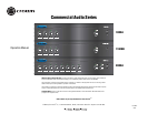
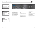
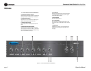
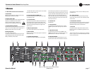
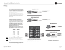
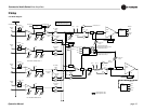
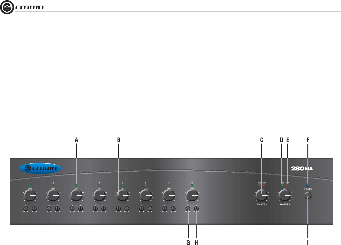
Figure 1.1 Front Panel Controls and Indicators
1 Welcome
1.2 Front Panel Controls and Indicators
A. Input Signal Presence Indicator
Green LED, one for each input channel, illuminates when
input signal exceeds –24 dBu (line) or –70 dBu (mic).
B. Input Volume Controls
Microphone/line, four in 180MA and 1160MA, eight in
280MA. Detented potentiometers with knobs.
C. Output Volume Controls
One per output channel. Detented potentiometer with
knob.
D. Output Signal Presence Indicator
Green LED, one for each output channel, illuminates
when output signal level exceeds 100 mV (45 dB below
full power) from the 4-ohm tap. Does not respond to sig-
nals from the AMP INPUT connector.
E. Clip Indicator
Red LED, one per output channel, illuminates at thresh-
old of audible distortion. Does not respond to signals
from the AMP INPUT connector.
F. Power Indicator
Blue LED indicates power on.
G, H. Tone Controls
Bass and Treble non-detented potentiometers on each
input channel. Bass ±10 dB at 100 Hz, Treble ±10 dB at
10 kHz.
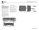
I. Power Switch
Pushbutton on-off switch. The power switch does not
affect the 24V DC auxiliary power input (letter “K” on
next page).