


Commercial Audio Series Mixer-Amplifiers
page 12
Operation Manual
2 Setup
2.11 Four-Tone Generator
Your mixer-amplifier can generate tones. The factory-preset tones include
Pre-Announce Chime, Bell, Alert Tone, and Evacuate Tone. All tones are
continuous except for Pre-Announce Chime. All tones are activated by
contact closures on the back panel. The Bell, Alert, and Evacuation tones
do not pass through the pre-amp outputs.
Tone levels (except for Pre-Announce Chime) are controlled by one trim-
pot for each amplifier output. Tone levels are not affected by the master
level control. Tones mute all signals except for priority signals from Ch.1
and Ch.5. When Ch. 1 or Ch. 5 mutes other signals, the tone and voice
signals are mixed.
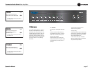
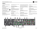
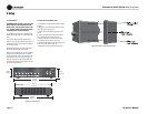
If you want to generate a tone, locate the TONE GENERATOR connector on
the back panel (Figure 2.12). Plug a 5-pin Phoenix-type cable connector
into that chassis connector. To activate the Pre-Announce Chime, wire a
SPST switch across COM and PRE-ANNOUNCE in the Phoenix-type cable
connector. Close the switch when you want the Chime tone to sound. Other
tones work in a similar way. Set the TONE GEN LEVEL potentiometer(s) for
the desired tone volume.
For example, you might put a magnetic contact closure switch in a door,
and wire it to the COM and PRE-ANNOUNCE pins. When the door opens,
the switch closes and the chime is activated.
The Pre-Announce Chime is mixed with Ch. 1 signals only. Its output level
is not affected by the Tone Gen Level controls.
Note: The Pre-Announce Chime works only on input Ch.1, not
input Ch. 5.
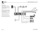
2.12 Powering Up
1. Turn off any equipment connected to the Line Out connectors.
2. Plug the amplifier’s power cord into a 3-wire grounded AC outlet.
3. Turn down the input volume controls.
4. Turn down the master volume control.
5. Turn on the Power switch. The Power indicator should glow.
6. Turn the input volume controls in use about 3/4 up.
7. Turn up the master volume control(s) until the desired loudness or
power level is achieved.
8. Touch up the input levels as needed for equal loudness from each
microphone.
9. Turn on any equipment connected to the Line Out connectors.
If you ever need to make any wiring or installation changes, disconnect the
power cord.
2.13 Included Accessories
Power cord
Detachable rack ears
Screws for rack ears
Non-touch cover for output connectors
Phoenix-type connectors
Spade lugs
2.14 Optional Accessories
1-VCAP remote volume control for one channel
4-VCAP remote volume control for four channels
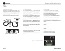
Figure 2.12 Tone Generator Connector
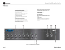
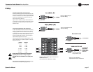
Figure 2.11 Wiring a 1-VCAP or 4-VCAP
Level Control to the Output VCA Connector
2.10 Remote Volume Control
You can control the volume of each amplifier channel remotely. To do so,
locate the OUTPUT VCA connector on the back panel. Insert a 4-pin Phoe-
nix-type cable connector into the OUTPUT VCA connector. Wire a Crown
1-VCAP or 4-VCAP level control to the Phoenix-type cable connector ter-
minals as shown in Figure 2.11.
1-VCAP controls one channel; 4-VCAP controls up to four channels.
Phoenix-type
plug
Output VCA Connector
Output VCA Connector