


page 9
Micro-Tech Series Power Amplifiers
Operation Manual
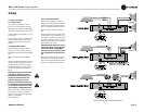
3.6 Wire Your System
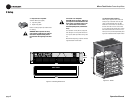
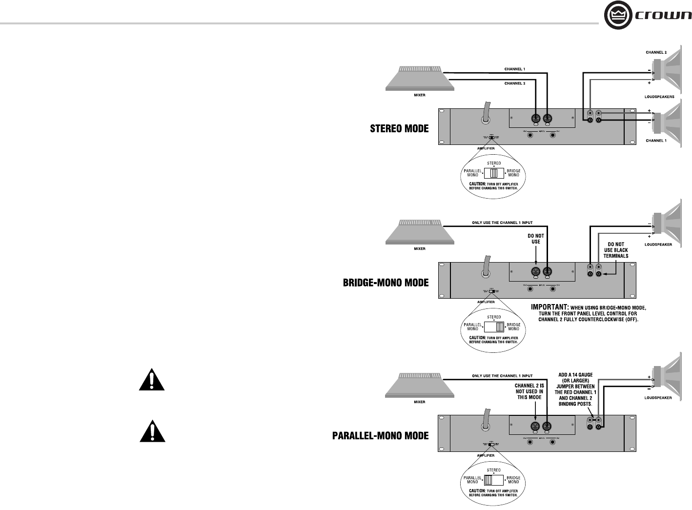
3.6.1 Stereo Mode
Typical input and output wiring is shown in
Figure 3.6. Turn off the amplifier, and set the
Stereo/Mono mode switch on the back to Stereo.
INPUTS: Connect input wiring for both channels.
OUTPUTS: Maintain proper polarity (+/-) on out-
put connectors.
Connect Channel 1 positive (+) speaker load to
Channel 1 positive terminal of amp; repeat for
negative (-). Repeat Channel 2 wiring as for
Channel 1.
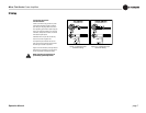
3.6.2 Bridge-Mono Mode
Typical input and output wiring is shown in
Figure 3.6. Turn off the amplifier, and set the
Stereo/Mono mode switch on the back to Bridge
Mono.
INPUTS: Connect input wiring to Channel 1
only.
OUTPUTS: Connect the speaker across the posi-
tive (red) terminals of each channel. Do not use
the negative terminals when the amp is being
operated in Bridge-Mono mode. The load must
be balanced so neither lead is connected to
ground.
CAUTION: Connect only balanced equip-
ment (meters, switches, etc.) to the
Bridge-Mono output. Both sides of the
line must be isolated from the input
grounds or oscillations may occur.
NOTE: To prevent distortion and low lev-
els, the Channel 2 level control should be
set fully counter-clockwise when operat-
ing the amplifier in Bridge-Mono mode.
NOTE: Crown provides a reference of wiring pin
assignments for commonly used connector
types in the Crown Amplifier Application Guide
(Section 1.21.) available at
www.crownaudio.com.
3 Setup
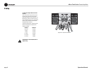
3.6.3 Parallel-Mono Mode
Typical input and output wiring is shown in
Figure 3.6. Turn off the amplifier, and set the Ste-
reo/Mono mode switch on the back to Parallel
Mono. Turn down the Channel 2 level control.
INPUTS: Connect input wiring to Channel 1
only.
OUTPUTS: Connect positive (+) speaker load to
amplifier Channel 1 red (+) binding post. Con-
nect negative (-) speaker load to amplifier Chan-
nel 1 black (-) binding post. Add a 14 gauge (or
larger) jumper wire between the red (+) binding
posts of both channels 1 and 2.
CAUTION: When the amplifier is wired for
Parallel-Mono mode, do not change the
rear switch to Stereo or Bridge-Mono.
Doing that will result in inefficient opera-
tion, high distortion and excessive heat-
ing.
NOTE: Crown provides a reference of wiring pin
assignments for commonly used connector
types in the Crown Amplifier Application Guide
(Section 1.21.) available at www.crownaudio.
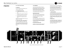
Figure 3.6 Three System Connection Methods