Getting Started
Unpacking................................. 4
Power Source........................... 4
Control Locators....................... 5-6
Basic Operation
General..................................... 7
Radio Operation....................... 7
Turntable Operation.................. 8
Cassette Operation.................. 8
CD Operation
Playing a CD............................... 9
Programmed Playback................ 9
Recording records to CD........... 10
Recording cassettes to CD........ 10
Erasing CD-RW CDs................. 11
Audio / Video Connections
Audio.......................................... 12
Video.......................................... 12
VCD Operation
Playing Video CD........................13
General
Troubleshooting Guide................ 14
Warranty....................................... 15
12
About This Manual
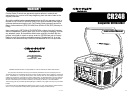
Thank you for purchasing the Crosley Songwriter
CD Recorder (CR248). Before operating this unit,
please read this manual thoroughly and retain it for
future reference.
Instructions in this manual describe the control
functions of the CR248.
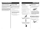
Included in the package:
Welcome
Table of Contents
Audio / Video Connections
Audio Connections
Songwriter CD Recorder
Remote Control
FM antenna
AM loop antenna
45 RPM adaptor
Turntable pad
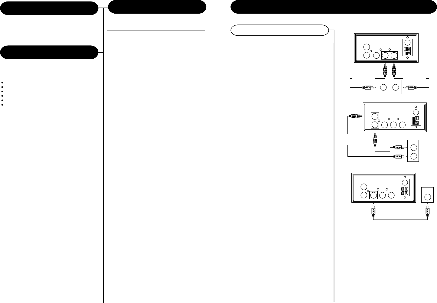
Aux Input
Using the Aux Input allows you to hook up additional
external audio components and listen to them through
your unit. Any component with an audio output such
as a Tuner, AV receiver or VCR, can be connected
by using the correct cables (not included). This unit
uses standard RCA cables. Simply plug the red and
white connectors on one end of the cable to the red
and white Aux In jacks on the back of your unit. The
other end of the cable will plug into the Audio Output
jack on the external component. For more information
on hooking up the external component, see the
owners manual for that component.
Audio Output
Using the Audio Output will allow you to run the
audio from your unit into a home stereo, television
or other stereo source. To make this connection,
you will need standard RCA cables. Plug the red
and white connectors on one end of the cable into
the red and white Audio O/P jacks on the back of
the unit. The other end of the cable will plug into the
Aux Input jacks of your selected component. For
more information on hooking up to the external
component, see the owners manual for that
component.
NOTE: You can still listen to your unit when using the Audio
Output feature
Line In Jack
The Line In Jack is located on the front of you unit.
This jack uses a 3.5 mm mini pin cable for connection.
This connection is especially useful in hooking up
smaller audio components like MP3 players. To
make this connection, you will need a 3.5mm audio
cable (not included). Hook one end of the cable into
the Line In Jack on the front of your unit. The other
end will plug into the Audio Output or headphone
jack on the selected component. For more information
on hooking up the external component, see the
owners manual for that component.
Video Connection
Your Songwriter will also play certain types of Video
Disks. This is covered on the following page. You
will need a RCA video cable (not included) to make
the connection. To make the video connection to
your television, connect one end of the video cable
to the yellow Video O/P jack on the back of your
unit. Connect the other end to the Video input jack
on your television.
If your television does not have the required Video
Input, you will need an RF Modulator (Radio
Frequency Modulator), which connects your TV
Antenna or cable line and serves as Video Input.
An RF Modulator can be purchased at almost any
consumer electronics retailer. If you are connecting
the video to either a television or a VCR video input
jack, you must specify the source the TV or VCR is
to display. Your TV or VCR user guide can tell you
how to display the video signal from the Video in.
jack.
NOTE: Some projection TV sets do not display the standard
blue background used on most VCD/ Jpeg/ Mpeg files disc
properly. If the background color is inconsistent or flashing,
please try connecting to a standard tube television.
Audio Output
Aux Input
Video Output
AUX IN
R
L
VIDEO O/P AUDIO O/P
L R
VIDEO OUTPUT
(YELLOW JACK)
VIDEO IN
VIDEO INPUT
(TV or VCR)
(YELLOW JACK)
FM
ANT.
AM
ANT.
AUX IN
R
L
VIDEO O/P AUDIO O/P
L R
AUX IN
L
(WHITE JACK)
FM
ANT.
AM
ANT.
ANOTHER
AUDIO COMPONENT
L
R
AUDIO OUT
AUX IN
R
(RED JACK)
AUX IN
R
L
VIDEO O/P AUDIO O/P
L R
L R
AUDIO IN
FM
ANT.
AM
ANT.
AUDIO OUTPUT
R
(RED JACK)
AUDIO OUTPUT
L
(WHITE JACK)


