


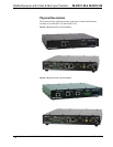
Crestron IM-RXV1-M & IM-RXV3-M iMedia Receiver with Video & Mic Input
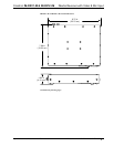
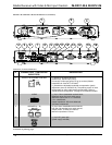
Connectors, Controls & Indicators (Continued)
#
CONNECTORS
1
, CONTROLS
& INDICATORS
DESCRIPTION
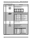
5 PWR LED (Green) indicates power connected to 18 VDC connector.
6 RESET BUTTON
SW-R - (1) Recessed pushbutton for software reset.
7
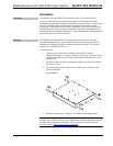
RELAY OUTPUT (1 – 2),
INPUT (1 – 3), IR, G
1
12
23 G
IR
(1) 9-pin 3.5mm detachable terminal block comprising:
(2) normally open, isolated relays;
(3) digital input ports referenced to ground;
(1) IR output port;
Relay rating: 2 Amp, 50 Volts AC/DC, MOV arc suppression;
Digital input rating: 0-24 Volts DC;
Digital input impedance: 2k ohms pulled up to 5 Volts DC;
Digital input logic threshold: 2.5 Volts DC nominal;
IR output frequency: Up to 1.2 MHz.
NOTE: IRP2 IR emitter probe sold separately.
8 INPUT LED (Red) indicates activity on any input port.
9 IR LED (Red) indicates activity on IR port.
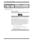
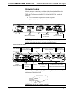
10
MIC
(1) 3.5mm TRS mini-phone jack;
Balanced mono line level audio input;
Maximum input level: 2 V
rms
balanced, 1 V
rms
unbalanced;
Input impedance: 18k ohms balanced/unbalanced.
Tip
Ring
Sleeve
Tip: Positive
Ring: Negative
Sleeve: Ground
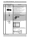
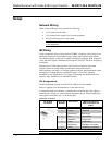
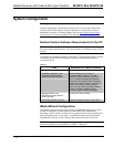
11 COMPUTER
(1) 6-pin RJ-11 female; computer console port. Use with
STCP-502PC serial cable (not included).
PIN # DESCRIPTION
1 CTS
2 GND
3 RXD
4 TXD
5 RTS
6 N/C (Not connected)
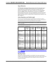
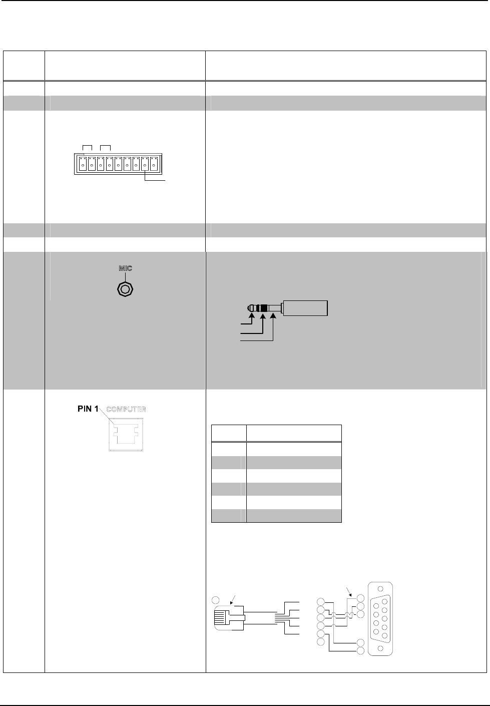
In the event that modular cables or an RJ-11 to DB9F adapter is not
available, the following diagram provides information so that the cable can
be fabricated on site. (Alternatively, Crestron cable number STCP-502PC
is sold separately.)
1
2
3
4
5
6
7
8
9
1
3
6
5
4
2
2
3
5
7
8
1
CTS
GND
RXD
TXD
RTS
n/c
TO PC
COM PORT
TO RS-232
PORT
Part #
748047-1
Part #
641337
Part #
AWC10152-A
(Continued on following page)
Operations & Installation Guide – DOC. 6593A iMedia Receiver: IM-RXV1-M & IM-RXV3-M • 9