


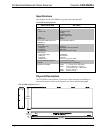

Professional Balanced Video Receiver Crestron CNX-PBVR4
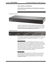
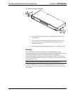
RCA Connectors
These four gold-plated RCA connectors provide flexibility to output component,
composite, and S-Video, along with digital audio for a variety of configurations
required by the local equipment in the room.
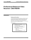
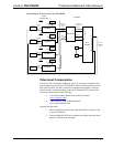
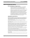
The four groups combined expand that flexibility, allowing for the simultaneous
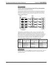
distribution of at least one of every video format. The simplified block diagram
following this paragraph illustrates the internal configuration of each I/O group.
VIDEO I/O Block Diagram
FIXED COMP
RCA
OUTPUTS
LEVEL 1
LEVEL 2
LEVEL 3
LEVEL 4
CAT5 INPUT
(FROM CNX-PVID8x3/4
or CNXRMCLV)
VIDEO
INPUT
COMP
2
3
1
2
4
3
1
1+
1–
2+
2–
3+
3–
4+
4–
1
2
3
6
4
5
7
8
RJ
-
4
5
Connector
Pins
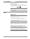
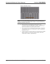
Although there is great flexibility to output a variety of video formats, certain
characteristics dictate the combination of video formats delivered by the CNX-
PBVR4. Characteristics include the internal wiring of the unit, the fact that three of
the four inputs can be compensated, and the ability to simultaneously distribute at
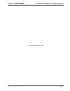
least one of every video format. The table after this paragraph lists three highly
recommended output configurations for the CNX-PBVR4 video I/O groups.
Recommended Output Configurations for CNX-PBVR4 I/O Groups
VIDEO
OUT
PORT
CONFIGURATION
A
CONFIGURATION
B
CONFIGURATION
C
1 Component (Y) S-Video (Y) Composite
2 Component (P
b
) S-Video (C) Composite
3 Component (P
r
) Composite
4 Digital Audio Digital Audio Digital Audio
PWR Indicator
The CNX-PBVR4 has a single PWR (power) indicator on its front panel. This LED
illuminates when the unit is connected to and receives 24VDC power from the
supplied power pack.
4 • Professional Balanced Video Receiver: CNX-PBVR4 Operations Guide – DOC. 8184