


Professional Balanced Video Receiver Crestron CNX-PBVR4
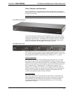
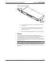
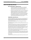
Ear Attachment for Rack Mounting
1. Using a Phillips screwdriver, remove the three side screws closest to
the front panel.
2. Position a rack ear so that its mounting holes align with the vacated
holes, and secure the ear to the unit with the three longer screws
supplied with the ears.
3. Repeat the procedure to attach the remaining ear to the opposite side.
Hookup
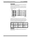
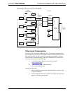
The CNX-PBVR4 provides great flexibility in redistributing video signals
throughout an entire home. Local room sources can now be distributed and shared to
other rooms through the headend. For example, as seen in the simplified
configuration diagram on the next page, users in Room 1 or Room 2 can choose to
view from among the headend sources, their own local sources, or the local sources
of the other three rooms.
NOTE: Terminators are not required on unused video output connectors.
To maintain highest signal integrity, Crestron recommends a maximum length of
300 feet for CAT5 input cables from the CNXRMCLV room solution boxes to the
CNX-PBVR4.
6 • Professional Balanced Video Receiver: CNX-PBVR4 Operations Guide – DOC. 8184