


Crestron CNX-PBVR4 Professional Balanced Video Receiver
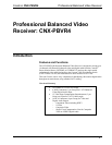
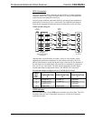
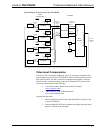
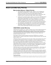
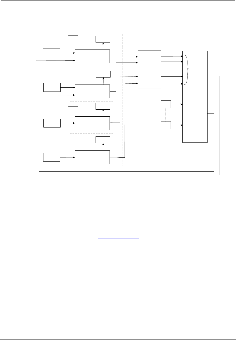
Typical Hookup Connections for the CNX-PBVR4
Local
Monitor/TV
Unbalanced
Video
Local
Monitor/TV
Unbalanced
Video
A
B
CNX-PBVR4
C
D
CNXRMCLV
CNXRMCLV
CNXRMCLV
CNXRMCLV
CAT5
CAT5
CAT5
CAT5
RCA (X4)
Room 1
Room 2
Room 3
Room 4
HEADEND
CNX-
PVID8x4
Balanced
Video/Digital
Audio
Unbalanced
Video/Digital Audio
RCA (X4)
RCA (X4)
RCA (X4)
Local Video
Source
Local Video
Source
DVD
Headend
Sources
Unbalanced
Video
Unbalanced
Video
Out
CAT5
CAT5
Out
In
In
Out
Out
Out
Out
In
In
In
In
In
Balanced
Video/Digital
Audio
(Max. I/O = 16 x 8)
ROOM
CONTROLLERS
Local
Monitor/TV
Unbalanced
Video
Local
Monitor/TV
Unbalanced
Video
Local Video
Source
Unbalanced
Video
Local Video
Source
Unbalanced
Video
In
In
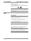
Video Input Compensation
After the system is completely hooked up, it may be necessary to adjust the video
input compensation pots on the CNX-PBVR4 to achieve the best picture on one or
more of the monitors. All that is required to complete this procedure is a narrow
slotted screwdriver and a third party audio/video calibration DVD (or laser disc).
Crestron recommends one of the following:
• Avia Guide to Home Theater from Ovation
Software
(www.ovationsw.com)
• Video Essentials from DVD International
(www.videoessentials.com).
Complete this procedure.
1. Place the third party audio/video calibration DVD (or similar) in the
system's DVD player.
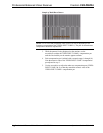
2. Search through the DVD for the chapter that displays the multi-burst
pattern, as shown on the next page.
Operations Guide – DOC. 8184 Professional Balanced Video Receiver: CNX-PBVR4 • 7