


FINAL SYSTEM CHECK
INPUT SENSITIVITY ADJUSTMENT
The Input Sensitivity Control is located on the Front Panel. The objective of input sensitivity
adjustment is to match the output of the source unit with the input of the amplifier. The output
voltage of individual source units can vary. For example, some radios have an output of 200 mV
and others have 5 Volts or more. To cater to these variations, the SE amplifier has an adjustable
input sensitivity level that ranges from 100 mV to 5 volts.
Adjusting this control requires some experimenting. Basically, you want all the gain at the begin-
ning of the system, NOT at the end (amplifier). Turn your headunit UP and keep your amplifier
gains at the minimum possible setting (counter-clockwise). This will give you the best sound and
lowest signal to noise ratio.
Besides better sonic reproduction, proper input sensitivity also helps to prolong the reliability
span of your amplifier by eliminating excessive internal temperature generated by incompatible
source unit output and amplifier input.
Note : Turning the input gain UP does NOT indicate MORE power. Just MORE noise. The input
gain control IS NOT a power control. REMEMBER that the input gain control has nothing to do
with the power output of the amplifier.
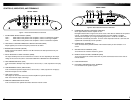
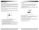
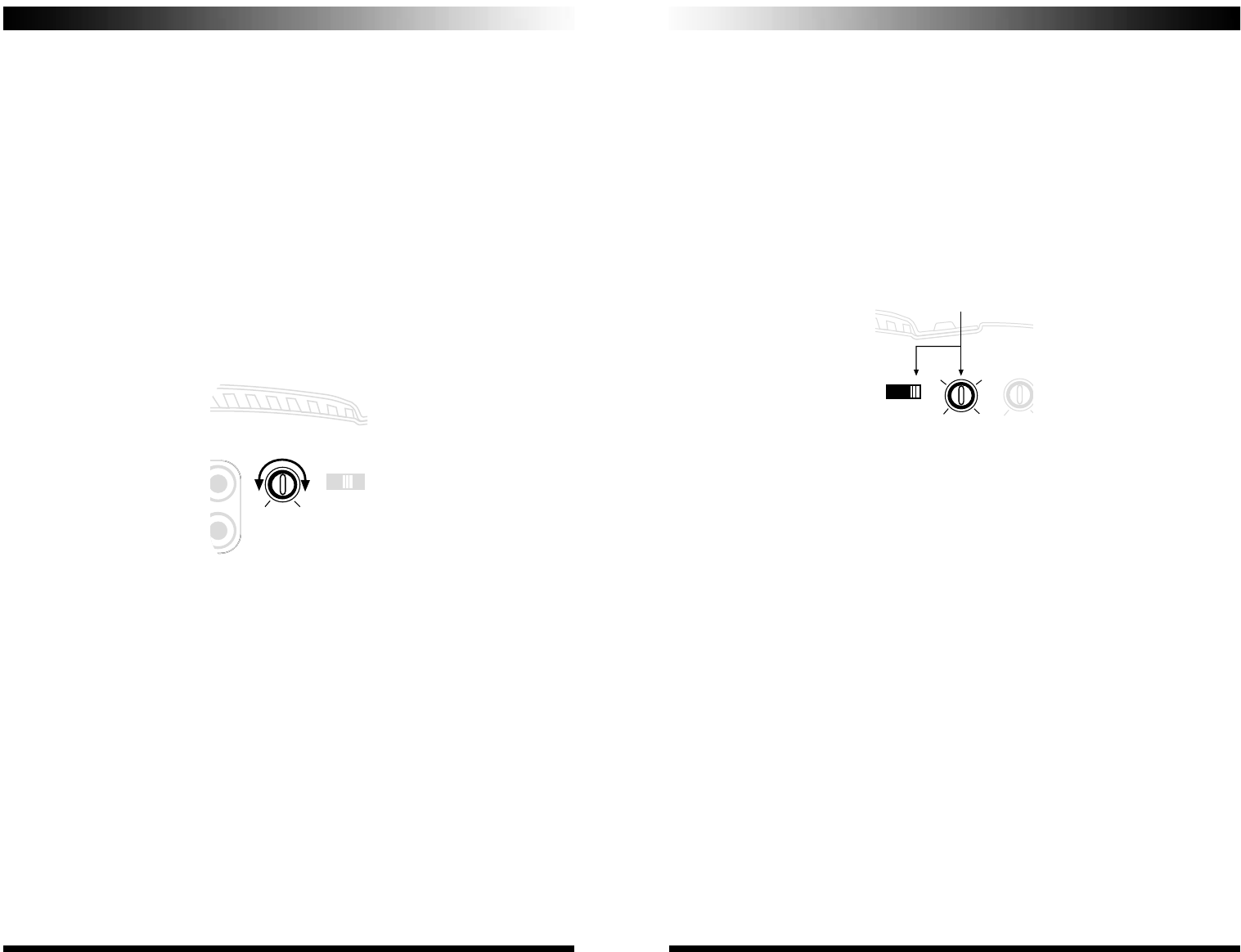
Figure 10: Input Sensitivity Control
1. Turn the Input Sensitivity Control all the way down (counter clockwise).
2. Set the volume control of the source unit to approximately 2/3 of its maximum output.
3. Turn the balance control of the source unit to its center position.
4. Leave the tone (bass/treble) controls at their usual position.
5. Play a CD or tape track with great dynamic range.
6. Use the Bass Boost Control to enhance the bass performance (if desired).
7. To locate the optimum input sensitivity setting, ask the person assisting you to turn the Input
Sensitivity Control clockwise until audio distortion starts to develop. Turn the sensitivity
control backwards slightly to minimize the distortion.
8. If you constantly switch between CD/tape and radio, you will need further adjustment since
radio output level differs from that of CD or tape. In this case, you need to locate a
balanced sensitivity setting which is best for both the output level of radio and that of CD or
tape.
CROSSOVER SELECTION
The amplifier has built-in high-pass/low-pass filters that can be defeated by sliding the switch to
the OFF position.
1. When the high-pass is selected, the amplifier will be devoted to mid/tweeters.
2. When the low-pass is selected, the amplifier will be used to drive woofers/subwoofers.
With this setting, the optional RS can directly control the amplifier playback level.
3. When the filter is switched off, the amplifier is used as a full range amplifier.
CROSSOVER FREQUENCY SELECTION
Both the high-pass and the low-pass section offer continuously adjustable crossover frequencies
between 30 and 300 Hz. Adjust the setting according to your speaker component specification or
to your particular preference.
Figure 11: Crossover Frequency Adjustment
BASS BOOST CONTROL (BOOST)
Select a boost level between 0 dB and +18 dB to enhance the bass performance for your sound
system. BASS BOOST is NOT free! Every 3dB of boost costs you twice as much in power.
Make sure to set the final gains ……after setting the Bass Boost to work best with your sub-
woofer/enclosure combination. More is NOT always better!
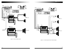
SETTING UP USING RS (Remote subwoofer control)
If you are using the RS control, make sure to take this into account during set-up procedures of
the subwoofer amplifier. You should set the system up with the RS plugged in, and with the level
knob turned all the way down (counter-clockwise).
NOTE: the RS ONLY works when you’ve selected the
LPF (low-pass) crossover configuration.
12
13
www.coustic.com
5 volts .1 volt
NPUTOUTPUT INPUT
30
180
SENS
MIN MAX
MODE
HPF OFF LPF
30
180
MODE
HPF OFF LPF
FREQ
30 300
60 180
0
BOOST
100Hz Low-pass selecte
MODE
HPF OFF LPF