


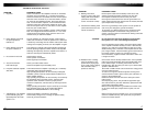


Connect the Amplifier to the Speakers. Use thicker speaker wires (e.g. 8 - 10 gauge desirable)
for these connections.
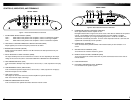
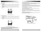
For Stereo Mode
1. Connect the left negative ("–") speaker output of the amplifier to the negative terminal of the
left speaker.
2. Connect the left positive ("+") speaker output of the amplifier to the positive terminal of the
left speaker.
3. Connect the right negative speaker output of the amplifier to the negative terminal of the
right speaker.
4. Connect the right positive speaker output of the amplifier to the positive terminal of the right
speaker.
Figure 7: Stereo Connection
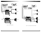
For Bridged (Mono) Mode
1. Connect the left positive ("+") speaker output of the amplifier to the positive input terminal of
the speaker.
2. Connect the right negative ("–") speaker output of the amplifier to the negative input terminal
of the speaker.
3. Make sure that BOTH RCAs (left/right) are plugged in, otherwise bass response and output
will suffer.
Figure 8: Bridged Single Woofer Connection
CAUTION: ANY DEVIATION FROM THE ABOVE SPEAKER CONNECTION MAY CAUSE
SERIOUS DAMAGE TO THE AMPLIFIER AND/OR SPEAKERS. PLEASE DOUBLE CHECK
THE CONNECTION BEFORE TURNING THE SYSTEM ON.
Connect the Amplifier to the Battery
Heavy gauge wire is preferred. Add a fuse or circuit breaker to any power wire that runs through
firewall or sheet metal to protect the battery, the vehicle, and more importantly, you. It is highly
recommended that installation is carried out by an authorized Coustic dealer.
Connect the Amplifier Remote Control
Connect the remote input terminal of the amplifier to the remote output terminal of the source unit
to establish amplifier remote on/off through the power on/off of the source unit. If the source unit
does not provide a remote output, connect to its power antenna lead or other switched 12-volt
source, e.g. ignition switch.
Connect the Amplifier Ground to Vehicle Chassis
Find a good ground spot in the vehicle and connect the ground terminal of the amplifier to this
point via a large gauge ground cable.
Reconnect the Battery Ground to the Vehicle Chassis
Double check all the previous installation steps, in particular, the wiring and component connec-
tion. If everything is in order, complete the installation by reconnecting the battery ground to the
vehicle chassis.
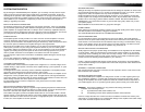
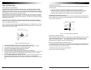
Optional RS Remote Subwoofer Level Control
If the optional remote subwoofer level control (model RS) is used, connect the plug of the RS to
the port on the end panel of the amplifier.
Figure 9: Remote Subwoofer Level Control.
10
11
www.coustic.com
BRIDGE
+ L - + R -
BRIDGE
+ L - + R -
T
SENS
MIN
MAX
MODE
HPF OFF LPF
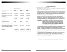
FREQ
30 300
60 180
0 +18
BOOST
REMOTE