COUSTIC.COM
11
INSTALLATION continued
INPUT CONNECTIONS
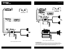
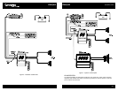
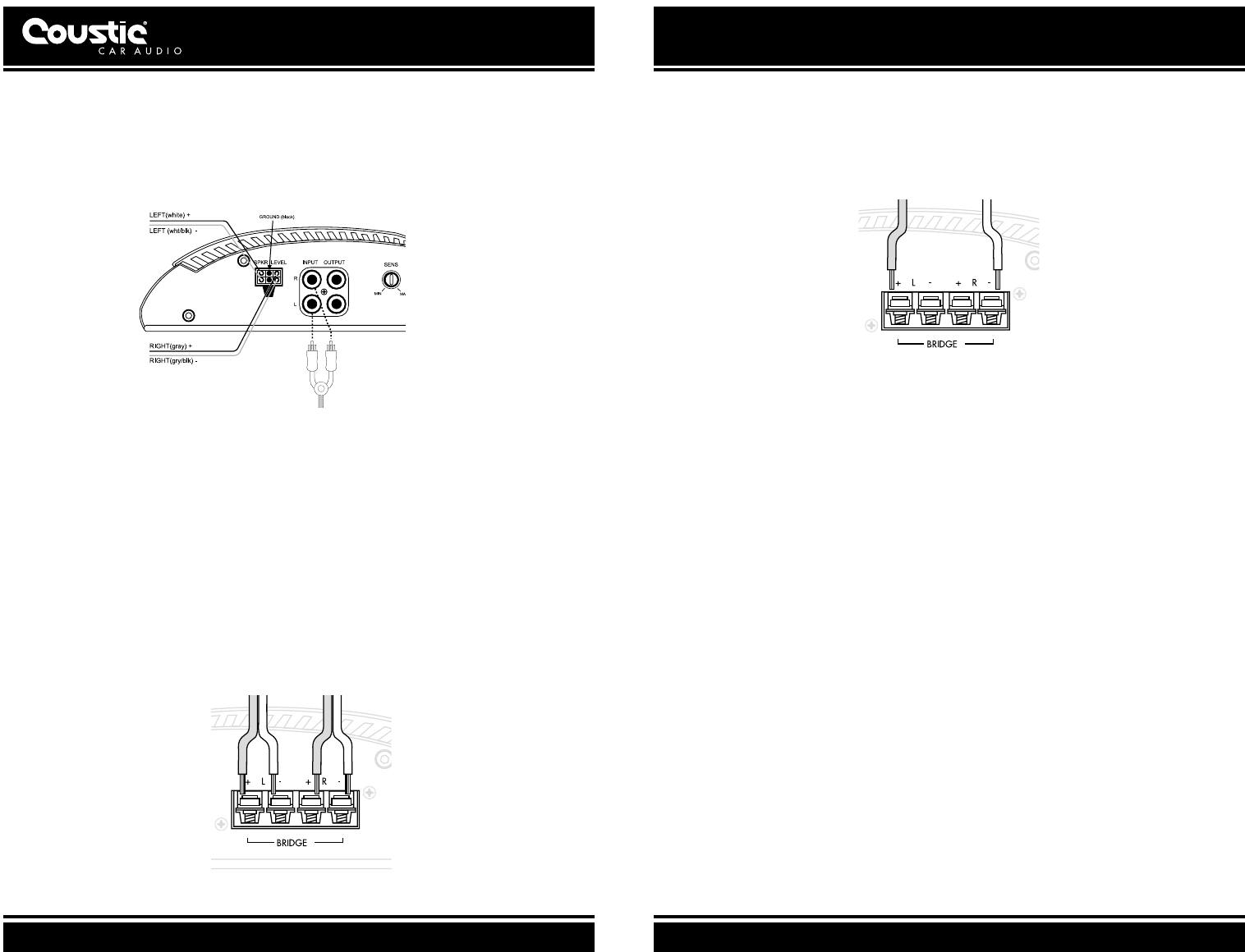
Connect the RCA input jacks of the Amplifier to the output of the Source Unit (i.e. radio, cassette
player or CD player). If line level output is not available, connect the speaker wires from the
source unit to the Speaker Level input of the amplifier.
Figure 8: High/Low Impedance Inputs
Note: Connect the black ground wire to the source unit ground only if alternator noise is
present.
SPEAKER CONNECTIONS
Connect the Amplifier to the Speakers. Use heavy gauge speaker wires (e.g. 8 - 10 gauge
desirable) for these connections.
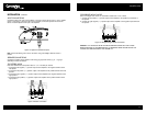
FOR STEREO MODE
Note: We recommend a total speaker load of 2, 4 or 8 ohms per channel
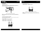
1. Connect the left negative ("–") speaker output of the amplifier to the negative terminal of the
left speaker.
2. Connect the left positive ("+") speaker output of the amplifier to the positive terminal of the left
speaker.
3. Connect the right negative ("–") speaker output of the amplifier to the negative terminal of the
right speaker.
4. Connect the right positive ("+") speaker output of the amplifier to the positive terminal of the
right speaker.
Figure 9: Stereo Connection
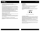
FOR BRIDGED MONO MODE
Note: For bridged mono mode, we recommend a total load of 4 or 8 ohms.
1. Connect the left positive ("+") speaker output of the amplifier to the positive input terminal of
the speaker.
2. Connect the right negative ("–") speaker output of the amplifier to the negative input terminal of
the speaker.
Figure 10: Bridged Single Woofer Connection
CAUTION: ANY DEVIATION FROM THE ABOVE SPEAKER CONNECTION MAY CAUSE
SERIOUS DAMAGE TO THE AMPLIFIER AND/OR SPEAKERS. PLEASE DOUBLE CHECK THE
CONNECTION BEFORE TURNING THE SYSTEM ON.


