1
THANK YOU FROM EVERYONE AT
CLASSÉ
Thank you for purchasing the Classé CA-101
power amplifier.
We take great pride in offering components that
combine exceptional sonic performance and
long-term reliability. To do that, we have invested
in extraordinary design and manufacturing
facilities. We trust that you will enjoy your
purchase for many years to come.
CLASSÉ DESIGN PHILOSOPHY
Repeated listening design sessions
Fine tuning of sound by exchanging and mixing
of parts (transistors, capacitors, wiring, PCB
boards etc.), and adjusting many specific
operating voltages within proper engineering
ranges, producing an overall sonic recipe giving
the most natural harmonic realism of music
typical of instruments in a live performance.
Upgradable single circuit designs
All Classé products (all preamps and all amps)
share exactly the same circuit (excluding moving
coil and moving magnet phono circuits). This
means all amplifiers and all high level circuits of
the preamps are the same. The same circuit is
tailored to different power levels etc. Differences
between less expensive models and more
expensive models are parts quality and
compliment, power supply extravagance and the
amount of filtering etc., as well as features and
packaging.
This means that for years Classé has been
constantly fine tuning and upgrading this circuit
and its application, thus reaching a very high
level of understanding and musical achievement
which benefits all models – least expensive, most
expensive, preamps and amplifiers alike.
Extreme long life in real world conditions
Choosing the best attainable quality parts and
materials combined with the advantages of the
two above-mentioned areas provides Classé
owners with years of proven trouble free
reliability and musical enjoyment.
UNPACKING & SET-UP
Your CLASSÉ CA-101 POWER AMPLIFIER is
packed in high density, semi-rigid foam placed in
a special cardboard box. To remove the unit,
open and spread all the top flaps of the box and
by its sides, lift out the entire unit and put it on a
large flat surface. Take it out of the plastic bag
and inspect the unit for any concealed damage.
Apart from this owner’s manual, please ensure
the following has also been included:
• DETACHABLE LINECORD.
Please report any damage or missing parts to
your dealer as soon as possible.
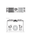
Place the CA-101 at or near its final set-up
position, allowing 8 inches at the rear for
tightening the speaker output connectors. For
optimum sonic performance, we recommend the
optional CLASSÉ REFERENCE A.C. LINECORD.
Consult your dealer regarding this accessory.
The power transformer in the CA-101 is located
at the front-center of the unit. Ideally, a few feet
should separate this area from components
which potentially could pick up hum. These
include preamplifiers, turntables, and
interconnect cables. In terms of providing
adequate airspace for cooling, a good rule of
thumb is to allow 6 inches above and 3 inches
on each side of the unit.
Check the Serial Number sticker on the back of
the unit for the correct operating voltage. The
CA-101 has one AC line fuse, the rating of
which should be as follows:
LINE VOLTAGE FUSE RATING
100 or 120 V.A.C. 6 AMP SLOW BLOW
125 or 250 volts
220 or 240 V.A.C. 4 AMP SLOW BLOW
250 volts
GENERAL CONNECTIONS
A.C. LINE
Insert the linecord into the A.C. receptacle on the
rear of the unit. PLEASE MAKE SURE YOU HAVE
PREVIOUSLY HOOKED UP THE SPEAKERS AND
PREAMPLIFIER TO YOUR AMPLIFIER BEFORE
CONNECTING THE AC POWER CORD TO THE
AMPLIFIER.
Caution: safety instructions
DISCONNECT THE AC LINECORD WHEN MAKING
OR CHANGING ANY CONNECTIONS. CONNECT
ALL INTERCONNECT CABLES BETWEEN YOUR
ELECTRONICS BEFORE CONNECTING THE AC
LINECORDS TO THE WALL OUTLETS. THIS WILL
REDUCE THE POTENTIAL SHOCK HAZARD.
“FLOATING THE GROUND”, OR DEFEATING THE
GROUND ON THE 3-PRONG LINECORD MAY
CREATE A SHOCK HAZARD.
STEREO
Input and output connectors are clearly marked
on the back of the amplifier. Left/Right
connections are oriented from the front of the
unit. Stereo output connections are marked
above the connectors. Switch stereo/mono switch
to /\ position. (Units preset at factory for
STEREO.)
Use only high quality interconnect and
loudspeaker cables, and make all connections
tight. If the input plugs are loose, remove them
and pinch down the ground leaves slightly with
pliers. Observe correct phasing of the
loudspeaker connections, and tighten.
MONO
Please read through the previous Stereo section
for general notes on securing good connections,
and safety tips. If the unit has been previously
used in stereo, make sure it is OFF, and remove
all connections, including the AC line cable.
Make sure the STEREO/MONO switch is switched
to the MONO position V.
The MONO “Input” is the “left channel input”,
as marked. The unused right channel input is
automatically disconnected. MONO output
connections are marked below the connectors.
Repeat the above MONO settings and
connections on the second CA-101 to be used
for the other channel.
Please remember that the negative output
connection of a bridged amplifier is NOT a
ground. Do not use a “common ground” or
switchbox set-up. Do not use with electronic
crossovers which have a common ground.
REMOTE CONTROL
The CA-101 can be turned on or off remotely
using the small Classe device called the
Automatic Starter (also called the Pigtail). When
the Automatic Starter is inserted into the
Telephone type jack at the back of the unit, the
CA-101 will automatically turn on as soon as
there is AC power present at the AC inlet of the
amplifier. You can then use a DC triggerable AC
power bar or inlet to turn on or off the CA-101.
Although the front power switch will not be used
under these circumstances, the front power
switch will still be operable.


