


6
PROTECTION
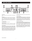
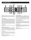
Every model in the CV-Series incorporates protection features. The front panel Protection LED indicates the activity of the speaker
connection relay circuitry in each channel. When the protection LED turns on, this circuitry is active, and all connected speakers are muted.
Initial power-up : For approximately five seconds after initial
power-up, the protection circuitry is activated and the speaker out-
p
uts are muted. If everything is operating normally, you will hear an
audible click at the conclusion of this brief period, as the protection
circuitry is deactivated and the unit begins delivering signal to the
connected speakers. It is normal for the Protection LED to fade
g
radually after the amplifier is powered off.
Thermal Protection : Abnormally high heat sink temperatures will
engage the protection circuitry for the overheating channel only.
An output relay disconnects the speakers until normal tempera-
ture range is restored. The Protect indicator will light to show the
protection circuit is active. To guard against this problem, make
sure the unit receives adequate ventilation on all sides and that
both the front and rear panels are unobstructed. If the power trans-
former gets too hot, its thermal switch will disconnect all of the sec-
ondary power and disconnect both channel outputs.
Short circuit : If output is shorted due to faulty wiring, the thermal
circuitry will automatically protect the amplifier. If this occurs, the
load will be disconnected by the thermal protection circuitry.
DC Voltage Protection : If an amplifier channel detects DC volt-
age at the speaker output, the output relay will immediately open
to prevent speaker damage.
Subsonic Frequency Protection : The built-in High Pass Filter
provides subsonic frequency protection for each channel.
Current limiting Protection : At the amplifier’s full power limit, or
clipping point, the limiter circuitry will be activated. This is indicated
by illumination of the Clip LED. The channel gain is automatically
r
educed, protecting the speakers from high power. Uncontrolled
feedback, oscillations, or improper equipment gain setting may ac-
tivate this circuitry, which is virtually transparent in operation as full
signal bandwidth is maintained.
There is reason to be concerned any time the Protection LED lights
up (except for initial power-up during approximately five seconds).
If this occurs, turn the amplifier off immediately and check all wiring
and external equipment carefully in order to locate and correct the
condition.
Clipping is the result of an amplifier running into power supply lim-
itation. The maximum output voltage that any amplifier can pro-
duce is limited by its power supply. Attempting to output a voltage
(or current) level that exceeds the power supply limit will result in
a flattening effect on the signal. A clipped waveform exhibits ex-
treme harmonic distortion, making it sound harsh or dissonant. The
clip limiter detects this and reduces the gain to minimize the
amount of overdrive. To preserve as much of the program dynam-
ics as possible, limiting reduces the average program level until
peaks barely clip. Each channel has its own clip limiter, which can
be switched on or off. When driving full-range speakers, clip limit-
ing reduces high frequency distortion caused by bass overload. It
also protects higher frequency drivers from excess overdrive and
harsh clipping harmonics.
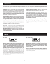
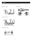
Clip limiter
Also known as a low-cut filter, a High Pass Filter rolls off signals
below 40Hz. The reproduction of the signal’s bass portion is thus
optimized, since ultrCV-low, distracting frequencies are eliminated,
and more power is available for the reproduction of the wanted
segment of the signal.
You should set up the filters so they best suit the frequency re-
sponse of your speakers, since some speakers are particularly
sensitive to over-excursion. The 40Hz filter works well with most
compact full-range speakers.
HPF (Hi-Pass Filter)
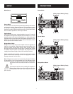
SETUP