


4
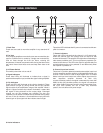
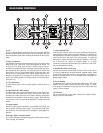
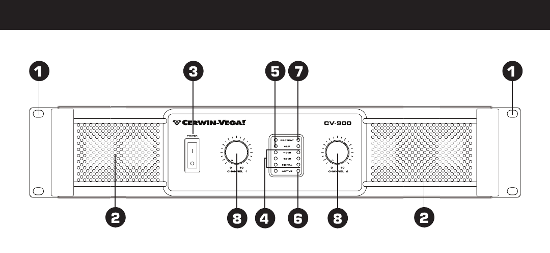
FRONT PANEL CONTROLS
1. Rack Ears
These ears are used to mount the amplifier in any standard 19”
rack.
2. Fan Vent
The CV-Series amplifiers are cooled by two rear-mounted fans (ex-
cept for CV-900 which is cooled by a single rear mounted fan).
Cool air flows through the front fan filters, reducing the
temperature of internal components while forcing the heat out the
rear vents. Never block these vents and keep them clean at all
time.
3. AC Power Switch
This switch powers the unit on and off.
4. Signal Indicators
These blue LED's will illuminate to indicate that a signal is
present at the amplifier input, and that the signal is being amplified.
5. Clip Indicators
These red LED's will illuminate at the clipping threshold. These
lights should not light up during normal use as they indicate
signal outside of the amplification range of the amplifier. When a
signal is "clipped" and the clip indicator illuminates, it means that
the signal is being distorted at the output stage. Prolonged
clipping can not only damage your amplifier, but also your
speakers, so be careful to monitor the clip indicator during setup
and use. If the clip indicator is illuminated then simply lower the
channel gain or input signal until the indicator does not light.
6. Active Indicators
These blue LED's indicate that AC power is connected and the am-
plifier is turned on.
7. Protect Indicators
These red LED's indicate that the channel is in Protect mode.
When the channel goes into protect mode all output for that
channel will be muted. The protect LED's light when overheating or
other severe problems occur. This is to protect any speakers con-
nected to the channel. The LED's also light for approximately five
seconds whenever the unit is powered on and fade slowly when
the amplifier is powered off.
8. Channel input level control
These two 21-position detented potentiometers adjust input level
for their respective amplifier channels. In Bridged Mono Mode, only
channel 1 level control is used to adjust signal level. In Parallel
Mode, both input level control are used to adjust signal level for
their respective amplifier channels. At their fully
counter-clockwise position, the signal is attenuated by more than
80dB. At their fully clockwise position, the signal is at maximum
gain. When 0 dBu of signal arrives at the input jacks and the Chan-
nel input level controls are set to their fully clockwise
position, the unit delivers full power output.