


5
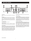
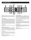
REAR PANEL CONTROLS
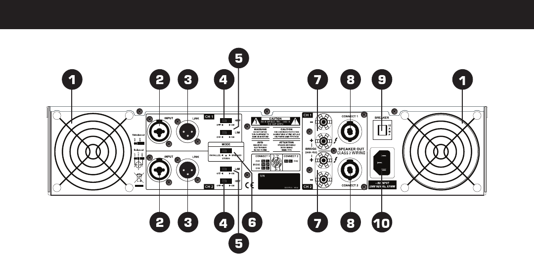
1. Fan
This is a variable speed cooling fan. Cool air enters the amplifier
through the fan filters located on the front of the amplifier. Be sure
not to block these ports when installing the amplifier or other equip-
ment.
2. Input connectors
Connect the input source to the balanced combo connectors using
either XLR or 1/4” TRS plugs. They are configured as follows : Pin
2 (Tip) hot, Pin 3 (Ring) cold, and Pin 1 (Sleeve) ground. We rec-
ommend using balanced three-conductor cabling wherever possi-
ble. Unbalanced two-conductor 1/4” plugs can also be inserted into
these inputs, but you will get better signal quality and less noise
and hum if you use balanced lines. Stereo signal should be con-
nected to the Channel 1 and Channel 2 input jacks. When operat-
ing the unit in Bridged Mono or Parallel modes, use the Channel 1
input jack only.
3. Link connectors
These jacks are used to send a parallel signal to another device or
amplifier.
4. High Pass Filter (HPF) switch.
These switches are used to activate the built-in High Pass Filter.
The HPF rolls off signals below 40Hz. This improves bass per-
formance by limiting sub-audio cone motion, making more power
available for the speaker’s rated frequency range. When the filter
is turned off, a 5 Hz roll off protects against DC or deep sub-audio
inputs.
5. Limiter switch
When the input signal connected to your amplifier is too high, you
end up with a distorted output signal. To prevent this, both chan-
nels feature a clip limiter that can be engaged or disengaged se-
lectively.
6. Bridge / Stereo / Parallel switch
This switch changes the amplifier operating mode between stereo,
mono bridged, and parallel.
7. 5-way Binding Post
Connect each channel of the unit to your speakers. Binding posts
are provided for each channel as well as Speakon
®
connectors, so
that paralleling of speakers is possible. Connection to the binding
posts can be made with bare wire, banana plugs, or spade lug
terminations. Make connections to both the Channel 1 and Chan-
nel 2 terminals for Stereo or Parallel Mode, or a single
connection across the red terminals only of Channel 1 and Chan-
nel 2 for Bridged Mono Mode.
8. Speakon® output connectors
You can use these to connect each channel of the unit to 8 ohms
or 4 ohms loudspeakers. Using Speakon® speaker cables, make
connections to both the channel 1 and channel 2 connectors for
Stereo or Parallel Mode, or to the Bridged mode connector for
Bridged Mono Mode.
9. Circuit breaker
The breaker acts in place of common disposable fuses. This circuit
breaker will trip if there is a fault with the main voltage or if maxi-
mum output is exceeded. Simply depress the circuit breaker and
power up the unit again.
10. AC input
IEC connector for AC power cable. Connect the supplied heavy-
gauge 3-pin IEC power cable.