


SC-407-10 Ver. B Installation and Operating Instructions Page 5 of 12
CP4842C 05/07/05
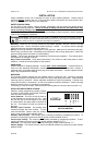
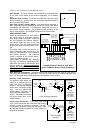
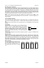
Horn Disable - The Horn function can be disabled by cutting the trace
on the back of the board at the location designated "cut to disable
horn".
Automatic Siren Disable - To disable automatic siren operation when
the lever switch is in position 3 cut and remove the red wire attached to
the lever switch relay board.
Horn Ring Cycler 2 option (HRC2) - This option allows selection of
Wail, Yelp, and Phaser by repeatedly pressing horn ring or other switch
connected to the AUX input. It is selected by cutting both the "AUX I"
and "PHSR" jumper resistors. This disables Phaser operation in the
Wail or Yelp positions. See OPERATION section for further details.
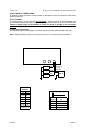
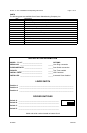
SIREN CONNECTIONS
Electrical connections to the siren section
are made using a removable terminal
block plug located on the back. A label on
the unit identifies the terminal function.
You should install the plug on the unit
before wiring. If the unit needs service the
plug can be easily removed without unwir-
ing.
The power supply of the unit must be ca-
pable of delivering peak currents up to 50
amps for adequate short circuit protection
and reliable operation. The preferred
source is directly at the vehicle battery.
The unit is internally fused.
Attach leads by stripping 3/8", inserting
into plug and clamp by tightening screw.
Make sure the screw is tight and the wire
can't be pulled out. Failure to adequately
tighten the screw can result in im-
proper operation or burning the con-
nector and wire.
Wire Size and Termination - The diagram shows the minimum wire size used for each connec-
tion, along with recommended lead color. If the wire is longer than 10 ft. use the next larger wire
size. Use only high quality crimp connectors for installation on the vehicle.
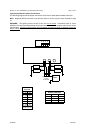
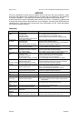
Auxiliary Input Connection -
The Auxiliary Input allows acti-
vation by an external source of
either the Horn or Man/Phsr
function. The adjacent diagram
shows three connection exam-
ples. See the INSTALLER-
SELECTABLE OPTIONS sec-
tion for programming details.
NOTE: Permanent disconnec-
tion of the vehicle horn is NOT
recommended.
Cutout Input Connection - The Cutout Input turns
off any siren tone output when activated, and remains
off until a control is activated or changed. The adja-
cent diagram shows two connection examples. See
the INSTALLER-SELECTABLE OPTIONS section for
programming details.
OPTION TRACE CUT
Cut to →
Disable horn
CONNECTIONS AT REAR OF UNIT WITH
10-PIN TERMINAL BLOCK PLUG (CP4688-10)
(2) #18 AWG BRN
(#16 - 2 SPKR)
2 - SPKR - Connect for
same phase (+ to +)
SPKR →
SPKR →
POS →
POS →
RAD →
RAD →
AUX →
CUT →
NEG →
NEG →
••••••••••
#22 AWG WHT (See below)
#22 AWG GRN (See below)
(2) #22 AWG BLU
Connect to output
jack, terminals or
speaker of radio
#14 AWG RED
Use second lead
for 2 - SPKR
#14 AWG BLK
Use second lead
for 2 - SPKR
RADIO
+
BAT
-
+VDC Switching examples
HORN
RING
SWITCH
+VDC
AUX
SPLICE
HORN
RING
SWITCH
+VDC
AUX
Added
SPDT
Switch
HORN
HORN
-VDC
switching
example
Must cut AUX P
option resistors
MOMENTARY
FOOT
SWITCH
AUX
-VDC
switching
example
Must cut CUT P
option resistors
ADDED
DOOR
SWITCH
CUT
+VDC Switching
example
DOOR
SWITCH
+VDC
CUT
SPLICE
DOME
LIGHT