


Page 4 of 12 SC-407-10 Ver. B Installation and Operating Instructions
05/07/05 CP4842C
INSTALLATION
Proper installation of the unit is essential for years of safe, reliable operation. Please read all
instruction before
installing the unit. Failure to follow these instructions can cause serious dam-
age to the unit or vehicle and may void warranties.
SAFETY PRECAUTIONS
For the safety of the installer, vehicle operator, passengers and the community please observe
the following safety precautions. Failure to follow all safety precautions and instructions may
result in property damage, injury or death.
Qualifications - The installer must have a firm knowledge of basic electricity, vehicle electrical
systems and emergency equipment.
Mounting - Mount the unit for easy access by the vehicle operator. DO NOT mount in air bag
deployment area. Assure clearances before drilling in vehicle. To prevent internal damage
mounting bolts must not enter case more than 1/4".
Wiring - Use wiring capable of handling the current required. Make sure all connections are tight.
Route wiring to prevent wear, overheating and interference with air bag deployment. Install and
check all wiring before connection to vehicle battery.
Testing - Test all siren functions after installation to assure proper operation. Test vehicle opera-
tion to assure no damage to vehicle.
Keep These Instructions - Keep these instructions in the vehicle or other safe place for future
reference. Advise the vehicle operator of the location.
UNPACKING
Inspect contents for shipping damage. If found alert carrier immediately
. Contents should in-
clude unit with attached microphone, mounting bracket, microphone bracket with 2 screws, 2
mounting bolts, removable terminal block plug, and these instructions. Contact supplier immedi-
ately if any components are missing.
MOUNTING
The mounting bracket supplied can be installed above or below the unit. Choose a mounting
location convenient to the operator and away from any air bag deployment areas. Inspect behind
mounting area for clearance. Assure adequate ventilation to prevent overheating. Consider wire
routing and access to connections, as well as microphone bracket placement. Install mounting
bracket to vehicle using 1/4" hardware (not supplied).
If mounting in a rack or console, make sure that mounting bolts do not enter case more than 1/4".
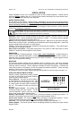
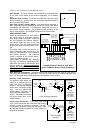
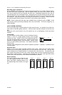
INSTALLER-SELECTABLE OPTIONS
Carefully cutting programming resistor jumpers
or traces on the printed circuit board inside the
case can select various options.
Cover Removal - The cover is held in place by
a snap-fastener on the back of the unit. Hold
the unit with the front case flange on the edge
of a hard surface and press hard on the back of
the unit. The chassis will slide out the front of
the cover.
Auxiliary Input Function - The auxiliary input
normally activates the Horn function. To acti-
vate the Man/Phsr function with the auxiliary
input cut the jumper resistor labeled "AUX I".
Auxiliary Input Polarity - The auxiliary input is normally activated by connecting to positive. To
activate by connecting to ground cut the two
jumper resistors labeled "AUX P".
Cutout Input Polarity - The cutout input is normally activated by connecting to positive. To acti-
vate by connecting to ground cut the two
jumper resistors labeled "CUT P".
Two-Tone - Two-Tone can replace Phaser by cutting the jumper resistor labeled "T-T".
Phaser Disable - The Phaser function can be completely disabled by cutting the jumper resistor
labeled "PHSR".
OPTION JUMPERS
FUSE
T-T
AUX I
PHSR
CUT P
AUX P
Sound Hazard
- Sound level from siren speaker (>120dBA @ 10 feet) may cause hearing damage.
Do not operate siren without adequate hearing protection for you and anyone in immediate vicinity.
(Ref. OSHA 1910.95 for occupational noise exposure guidelines)