


SA-500-27 14 Installation and Operating Instructions Page 7 of 12
CP5015A 09/09/08
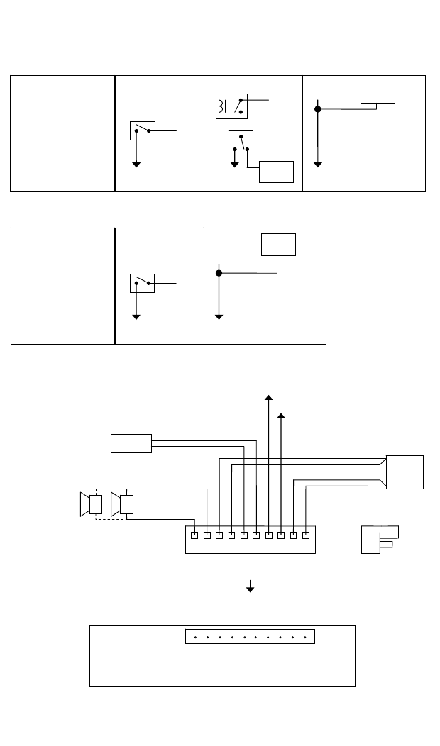
ELECTRICAL CONNECTIONS CONTINUED
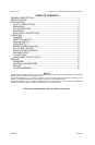
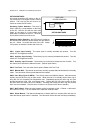
Auxiliary Input
Connection Examples
Activated with
+VDC OR -VDC
Factory Default
DIP SW-2 ON for +VDC
DIP SW-2 OFF for -VDC
HORN RLY
+VDC
or
-VDC
Added
SPDT
S
wit
c
h
To
AUX
Vehicle
Horn
+VDC
or
-VDC
Momentary
SPST
S
wit
c
h
To
AUX
Horn
Circuit
Note:
Vehicle horn will also
sound with siren
To
AUX
Vehicle
Horn
S
p
lice
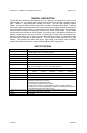
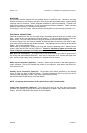
Cutout Input
Connection Examples
Activated with
+VDC OR -VDC
Factory Default
DIP SW-1 ON for +VDC
DIP SW-1 OFF for -VDC
+VDC
or
-VDC
Momentary
SPST
S
wit
c
h
To
CUT
Door
Switch
Circuit
To
CUT
Dome
Light
S
p
lice
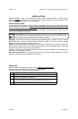
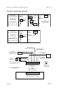
Plug into unit first for
terminal identification
10-P Terminal Block Plug
(CP4688-10)
Plug installed
thi
s
o
ri
e
nt
a
ti
o
n
+
-
#16 AWG BRN
(2 LEADS)
+
-
BAT
#14 AWG BLK
(2 LEADS)
#14 AWG RED
(2 LEADS)
#22 AWG GRN
(CUT) Cutout Input
RADIO
100W
Speaker(s)
#22 AWG BLU (2 LEADS)
SPKRÆ
SPKRÆ
POSÆ
POSÆ
RADÆ
RADÆ
AUXÆ
CUTÆ
NEGÆ
NEGÆ
Connect to
output jack, terminals
or speaker of radio
#22 AWG WHT
(AUX) Auxiliary Input
20A Automotive Type Fuse
is inside unit
+
-
Connect second speaker
for same phase (+ to +)