


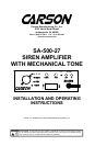

Page 6 of 12 SA-500-27 14 Installation and Operating Instructions
09/09/08 CP5015A
MOUNTING
The mounting bracket supplied can be installed above or below the unit. Choose a mounting
location convenient to the operator and away from any air bag deployment areas. Inspect behind
mounting area for clearance. Assure adequate ventilation to prevent overheating. Consider wire
routing and access to connections, as well as microphone bracket placement. Install mounting
bracket to vehicle using 1/4" hardware (not supplied).
If mounting in a rack or console, make sure that mounting bolts do not enter case more than 1/4".
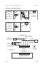
ELECTRICAL CONNECTIONS
Electrical connections to the unit are made using a removable terminal block plug located on the
back. A label on the unit identifies the terminal function. You should install the plug on the unit
before wiring. If the unit needs service the plug can be easily removed without unwiring.
The power supply of the unit must be capable of delivering peak currents up to 50 amps for ade-
quate short circuit protection and reliable operation. The preferred source is directly at the vehicle
battery. The unit is internally fused.
Attach leads by stripping 3/8", inserting into plug and clamp by tightening screw. Make sure the
screw is tight and the wire can't be pulled out. Failure to adequately tighten the screw can
result in improper operation or burning the connector and wire.
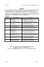
Wire Size and Termination - The diagram shows the minimum wire size used for each connec-
tion, along with recommended lead color. If the wire is longer than 10 ft. use the next larger wire
size. Use only high quality crimp connectors for installation on the vehicle.
Radio Input Connection (Optional) - Connect 1 lead to each terminal of the radio speaker or
output connector. The input is isolated and polarity is not important. May need to set Radio Vol-
ume on front of unit.
Auxiliary Input Connection (Optional) - The Auxiliary Input allows activation by an external
source of either the Horn or Manual function. Typically connected to the horn ring circuit of the
vehicle or other momentary switch. May need to set activation polarity.
See OPTION SWITCHES section for further details.
NOTE: Permanent disconnection of the vehicle horn is NOT recommended.
Cutout Input Connection (Optional) - The Cutout Input turns off any siren tone output when
activated, and remains off until a face control is activated or changed. May need to set activation
polarity. See OPTION SWITCHES section for further details.