


TB0349A Page 8 of 12 09/22/05
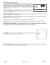
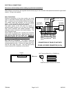
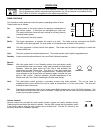
Light Control Rocker Switch Connections
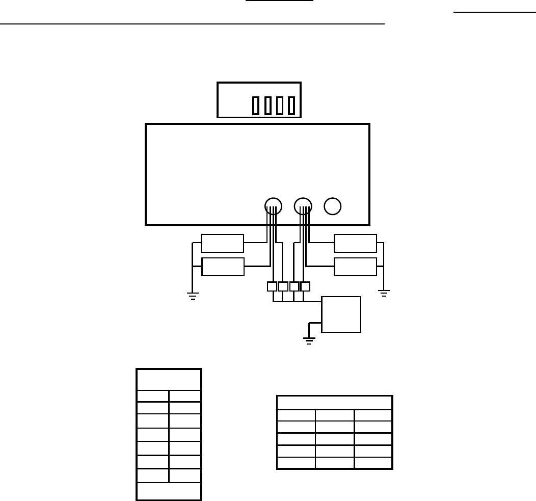
The following diagram shows proper connection of the rocker switch leads located at the rear.
Note: Negative (NEG) connection must also be made on 10-Pin connector for rocker switches to light up.
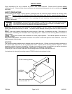
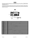
WARNING: The lighting control circuits of this unit are not fused
. Automotive fuses or circuit breakers must be
connected between the power source and the unit properly rated for the circuit requirements. Failure to install
proper circuit breakers or fuses can result in damage to the unit and/or vehicle.
GRN
Recommended
Wire Size
Amps Size
5 - 10 #16
10 - 15 #14
15 - 30 #12
30 - 40 #10
40 - 50 #8
50 - 60 #6
Use next larger size
if longer than 10 ft.
GRN
BLU
Circuit Breakers
or Fuses
20 AMP Max.
LOAD A
LOAD B
LOAD C
+
BATT
-
A B C D
LOAD D
A B C D
BLU
RED
YEL
RED
YEL
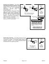
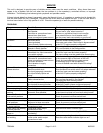
Switch Leads Hole
A GRN/YEL Center
B BLU/RED Center
C GRN/YEL Left
D BLU/RED Left
Switch Lead Sets