


TB0349A Page 5 of 12 09/22/05
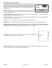
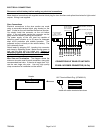
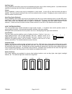
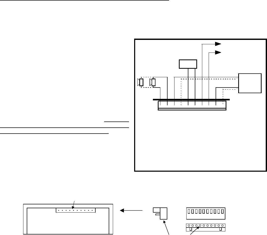
CONNECTIONS AT REAR OF UNIT WITH
CP4688-10 POWER CONNECTOR (10-Pin)
(2) #18 AWG BRN
(#16 - 2 SPKR)
2 - SPKR - Connect for
same phase (+ to +)
SPKR →
SPKR →
POS →
POS →
RAD →
RAD →
AUX →
CUT →
NEG →
NEG →
••••••••••
#22 AWG WHT (See below)
#22 AWG GRN (See below)
(2) #22 AWG BLU
Connect to output
jack, terminals or
speaker of radio
#14 AWG RED
Use second lead
for 2 - SPKR
#14 AWG BLK
Use second lead
for 2 - SPKR
RADIO
+
BAT
-
ELECTRICAL CONNECTIONS
Disconnect vehicle battery before making any electrical connections.
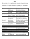
Make electrical connections with supplied terminal block plug for siren functions and spliced lead wires for light control
outputs. Wiring is not supplied.
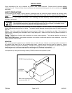
Siren Connections
Electrical connections to the siren section are made
using a removable terminal block plug located on the
back. A label on the unit identifies the terminal function.
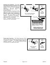
You should install the connector on the unit before
wiring. If the unit needs service the connector can be
easily removed without unwiring the connector.
The power supply of the unit must be capable of
delivering peak currents up to 50 amps for adequate
short circuit protection and reliable operation. The
preferred source is directly at the vehicle battery. The
unit is internally fused.
Attach leads by stripping 3/8", inserting into connector
and clamp by tightening screw. Make sure the screw is
tight and the wire can't be pulled out. Failure to
adequately tighten the screw can result in improper
operation or burning the connector and wire.
Wire Size and Termination - The diagram shows the
minimum wire size used for each connection, along with
recommended lead color. If the wire is longer than 10 ft.
use the next larger wire size. Use only high quality
crimp connectors for installation on the vehicle.
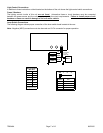
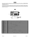
10-P Terminal Block Plug (CP4688-10)
Header
Install with screw terminals face down