


TB0349A Page 6 of 12 09/22/05
+VDC Switching examples
Must cut AUX P option resistor
HORN
RING
SWITCH
+VDC
AUX
SPLIC E
HORN
RING
SWITCH
+VDC
AUX (Add resistor to GND)
Added
SPDT
Switch
HORN
HORN
-VDC
switching
example
MOMENTARY
FOOT
SWITCH
AUX
ADDED RESISTOR FOR
POSITIVE SWITCHING
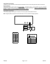
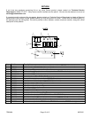
SPKR →
SPKR →
POS →
POS →
RAD →
RAD →
AUX →
CUT →
NEG →
NEG →
••••••••••
Added r esistor to GND
1K @ 1/4 watt
-VDC
switching
example
ADDED
DOOR
SWITCH
CUT
+VDC Switching
Example
Must cut CUT P option resistor
DOOR
SWITCH
+VDC
CUT
SPLICE
DOME
LIGHT
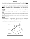
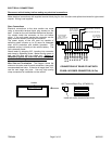
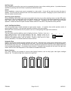
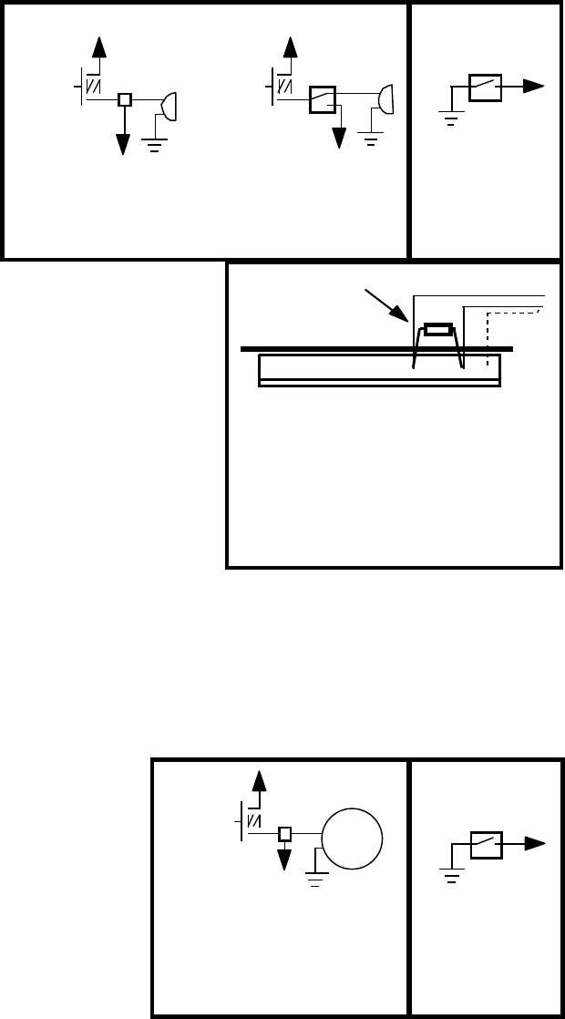
Auxiliary Input Connection - The Auxiliary
Input allows activation by an external source
of either the Horn or Man/Phsr function. The
adjacent diagram shows three connection
examples. See the INSTALLER-
SELECTABLE OPTIONS section for
programming details.
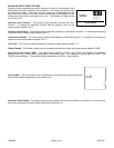
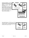
If positive switching is used for the auxiliary
(AUX) Input and the connection to the
destination device (horn) is removed a
resistor (1 supplied) must be added between
the AUX input and ground for proper
operation. A symptom of this problem is
continual activation of the auxiliary function
when the horn ring is not pressed.
NOTE: Permanent disconnection of the
vehicle horn is NOT recommended.
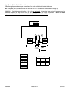
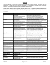
Cutout Input Connection - The Cutout Input turns off any
siren tone output when activated, and remains off until a control
is activated or changed. The adjacent diagram shows two
connection examples. See the INSTALLER-SELECTABLE
OPTIONS section for programming details.