


Input B Input A
In C In A
1 321 32 1 321 32
In BIn D
Input CInput D
+ - + - + - + -
Input B Input A
In C In A
2
3
12
3
1 2
3
12
3
1
In BIn D
Input CInput D
+-
+-+-+-
3 INSTALLATION
USER MANUAL
Q-P OWER S ER IES
P. 13
Q - P O W E R
SERIES
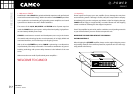
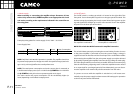
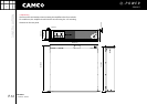
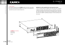
3.4 Cooling
Under normal operation of the power amp, overheating should never be a
problem. The air is taken in from the front and out through the back. It is of
course essential that while the power amp is running air is able to circulate
around it freely.
The efficiency of the cooling will depend on the immediate environment (e. g.
an enclosed rack, direct sunlight) and on whether the front filter is clogged. If
the amp is installed in a case the open area at the back of the case must be at
least 140 cm². This area should be in line with the amp.
If this can not be achived a forced ventilation system has to be used.
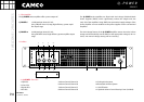
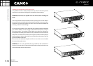
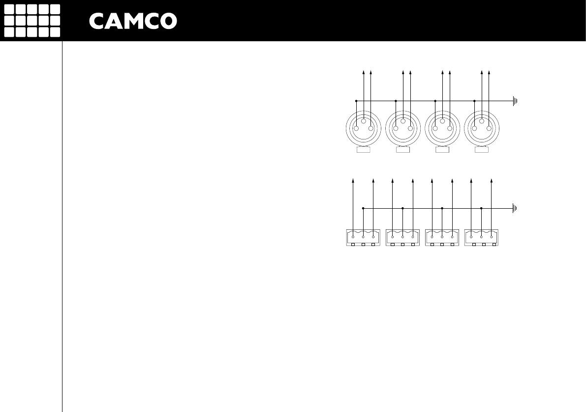
3.5 Wiring
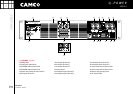
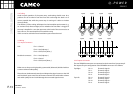
3.5.1 Input Connectors
XLR: Pin 1 = Ground
Pin 2 = Hot (inphase, +)
Pin 3 = Cold (out of phase, -)
Euroblock connector: Pin 1 = Hot (inphase, +)
Pin 2 = Ground
Pin 3 = Cold (out of phase, -)
Make sure to always use high-quality symmetrical (balanced) shielded cable to
ensure maximum audio quality.
Please do not simultaneously attach two independent signal sources to the XLR
and Euroblock input connectors of the same channel. This could lead to volume
and audio quality loss and could damage the connected signal sources.
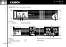
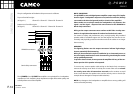
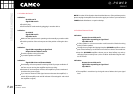
3.5.2 Output Connectors
The two SPEAKON connectors are connected to the channel A to D power ampli-
fier outputs. The pin configuration of the SPEAKON-connectors is as follows:
Top Right: Pin 1+ Channel A signal +
Pin 1- Channel A signal -
Pin 2+ Channel B signal +
Pin 2- Channel B signal -
Top Left: Pin 1+ Channel C signal +
Pin 1- Channel C signal -
Pin 2+ Channel D signal +
Pin 2- Channel D signal -