


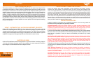
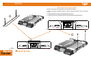
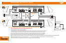

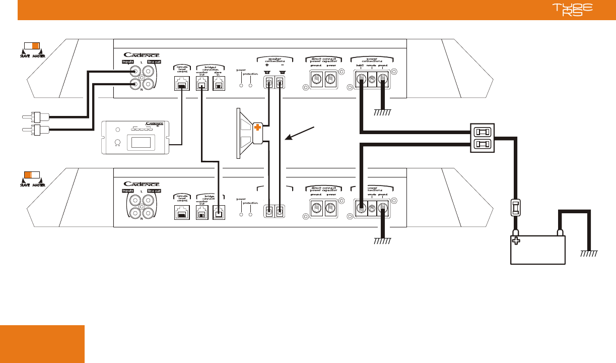
MASTER/SLAVE CONNECTION DIAGRAM
MONO BRIDGING 2 AMPLIFIERS INTO 1 WOOFER10
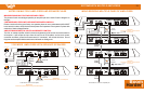
Mode switch
Mode switch
2 ohm
minimum
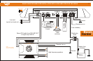
AMPLIFIER MODE SWITCH, INPUTS AND REMOTE CONTROL
Set the AMPLIFIER MODE switches as shown
Connect the source to the master amplifier inputs, and an optional CPR remote control to the master, as shown.
Use a PM2 bridging cable to connect the master output of the first amplifier to the slave input of the second.
Connect the speaker as shown, with the link between the negative speaker terminals of the two amplifiers.
Connect the ground terminal with as short a piece of cable as possible to the nearest metal chassis point.
Mount a master fuse right at the battery + terminal as shown. Add up the current draw for all amplifiers in the system to determine the rating for this fuse.
Use a power distribution block, such as the Cadence FH-1, FH-2 or FH-3 at the amplifier location to supply +12 volt to each amplifier.
Connect the remote turn on signal from the source to all amplifier remote turn on terminals.
NOTES ON MONO BRIDGING 2 RS AMPLIFIERS INTO ONE SPEAKER LOAD
Ground
Ground
Master fuse
at battery
Distribution
block
IMPORTANT:
Link between 2 amplifier
- speaker terminals
#14 minimum
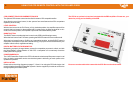
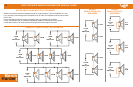
BURST
LEVEL
FULL POWER
FULL
POWER
-50 dB
POWER
PRPR
BATTERY
VOLTAGE
Battery
Boom
!
Harder
Pm2
Cable