


PHONO EQUALIZATION MODULES (Optional):
Bryston’s phono equalizer circuitry is available in both BP20
and BP25 pre-amplifiers. It features highly accurate equal-
ization, extremely low noise and distortion and provides
headroom margins sufficient to prevent overload from any
known phono source. If your turntable provides a separate
ground lead , system noise may be minimized by connect-
ing it to the ground post adjacent to the phono inputs on the
rear panel.
Moving Magnet Phono Cartridge Input (MM):
This is Bryston’s standard RIAA phono equalization stage. It
is found in both the “-P” and “-MC” versions of the BP20/25
pre-amp. Input impedance is 50K ohms and sensitivity is
5mV.
Moving Coil Phono Cartridge Input (MC):
Moving coil phono cartridges require much more gain than
the more common moving magnet types. To accommodate
moving coil cartridges Bryston offers the BP20MC/BP25MC
pre-amps which include specially designed, custom made
step-up transformers in addition to Bryston’s standard RIAA
phono equalization stage found in the “-P” versions of the
BP20/25 pre-amp. Which phono equalization stages are
engaged is determined by the front panel toggle switch
labeled “MC Phono / MM Phono”. This switch is not present
on the BP20P/BP25P models; it is replaced, instead with a
“Mono / Stereo” switch. Please note that it is important that
your phono cartridge is connected to the correct inputs in
order to achieve proper performance.
Input impedance is 180 ohms and sensitivity is 350uV.
DIGITAL AUDIO INPUT MODULE (Optional):
The BP20DA / BP25DA models contain two SPDIF com-
patible digital audio inputs. To select either the DAC-1 or
DAC-2 digital audio input, first set the rotary SOURCE
selector to DAC, and then select between the two SPDIF
inputs with the DAC-1/ DAC-2 toggle switch. The digital-to-
analog convertor can handle input sample rates from
16KHz to 108KHz, and word lengths of 16, 18, 20 or 24
bits.
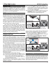
VISUAL INDICATORS:
MPS1 Power Supply: The LED on the front panel of the
MPS1 lights GREEN when power is on and RED when the
power is on but the main outputs are muted by having acti-
vated either the “Mute/Normal” toggle switch (on the pre-
amp’s front panel) or the “MUTE” button on the hand held
remote control.
BP20/25: The three colour LED (light emitting diode)
located on the front panel lights RED when the output is
muted, GREEN when the output signal is non-inverting
polarity and YELLOW when the output signal is inverted
with respect to the input. When the LED is unlighted, the
power is off.
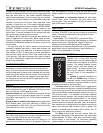
FRONT PANEL CONTROLS:
MUTE/NORMAL TOGGLE SWITCH: Mutes or releases
mute at the main outputs, (not ‘To Tape’ outputs), without
changing the volume control setting, each time pushed.
POLARITY/INVERT TOGGLE SWITCH: Reverses polari-
ty at main output5 each time pushed. (GREEN LED indi-
cates positive polarity, YELLOW LED indicates inverse
polarity).
VOLUME CONTROL: Rotary control varies the output
level to the ‘MAIN OUTPUTS’, (does not effect ‘TO TAPE’
outputs). BALANCE: Rotary control adjusts the left-versus-
right channel levels.
BALANCE CONTROL: is a tailored-inflection type which
has very gradual action near the center of rotation allow-
ing fine adjustments to the stereo image. For convenience
the electrical center of the control is detented.
SOURCE SELECT SWITCH: Rotary switch determines
which input will appear at the “TO TAPE” outputs for
recording or processing, as well as determining which pro-
gram is available at the Main outputs. (When the
“TAPE/SOURCE” switch is in “Tape” position, “FROM
TAPE” inputs appear at Main Outputs).
MONO/STEREO SWITCH: “Stereo” position provides
two-channel stereo at the Main outputs. ‘Mono’ position
sums the main outputs to monaural. The ‘TO TAPE’ out-
puts are always stereo. (Switch not present on “-MC” or “-
DA” models).
MC/MM PHONO SWITCH: This switch is present on the
BP20MC & BP25MC models only. It allows the selection
of either Moving-Magnet or Moving-Coil phono equaliza-
tion. This switch takes the place of the “Mono/Stereo” tog-
gle switch on other BP20/25 models.
DAC-1/DAC-2 TOGGLE SWITCH: Only on BP20DA &
BP25DA models, this switch determines which of the two
SPDIF digital audio inputs is processed and then sent to
the tape and main outputs. The SOURCE select switch
must also be in the “DAC” position to monitor the digital
audio inputs.
TAPE/SOURCE SWITCH: “Source” position monitors
whichever input is selected at the rotary SOURCE selector
rotary switch. “Tape” position provides monitoring of the
“FROM TAPE” input for A/B comparison with the source.
Should an external processor or equalizer be connected in
the tape loop, the ‘TAPE / SOURCE” switch will act as an
in/out switch for the external equipment.
5
BP20/25 PreAmplifiers