


Connect the pre-amplifier's left and right outputs from either
the RCA or Balanced XLR connectors to the appropriate left
and right input jacks on your power amplifier. Balanced
cables are an advantage if you are using long runs of cable,
(greater than 20 feet), between your preamplifier and power
amplifier. Connect your CD player, tuner, tape deck, video
recorder, or laser disc, etc. to the specific left/right pream-
plifier inputs.With phono-equipped models, (BP20P, BP25P,
BP20MC, BP25MC) connect your phono cables to the
phono input jacks. If your turntable leads have a separate
ground wire, it may be connected to the ground post adja-
cent to the phono inputs on the rear panel.
The Bryston BP-20 and BP-25 pre-amps also feature two
pairs of balanced XLR input jacks. Many signal sources,
including CD-players and separate D/A converters are now
available with Balanced outputs for minimum noise pickup
on the cables.
The tape loop may be used to insert a surround sound
processor, cassette tape deck or video tape recorder into
your system. Plug your tape deck or external processor's
input cables into the “To Tape” jacks, and the processor or
deck's output cables into the “From Tape” jacks at the rear
of the pre-amp. The tape or processor loop may be operat-
ed via the “Tape/Source” toggle switch located on the front
panel of the preamplifier.
HEADPHONE OUTPUT:
It is recommended that you use headphones with an
impedance of greater than 50 ohms for optimal perform-
ance. The main outputs, both balanced and single-ended,
will be muted when a phone plug is inserted into the head-
phone jack (TAPE outputs are not muted). The front panel
indicator LED will not turn red, however, as is does when
the outputs are muted via the MUTE toggle switch or the
hand held remote control.
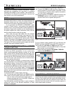
INPUTS:
BP20/25 preamplifiers are equipped with five pairs of RCA
input connectors: two paris of balanced XLR input connec-
tors, and one pair of RCA tape input jacks.
Balanced inputs use 3 pin XLR female connectors with pin
1 being ground, pin 2 as positive signal, and pin 3 as nega-
tive signal. Input sensitivity is 1 volt and input impedance is
15K ohms.
Single-ended (or unbalanced) inputs employ gold plated
RCA (Phono) jacks. Line input sensitivity is 500mV and
input impedance is 50K ohms.
See also PHONO EQUALIZA-
TION MODULES for Phono input details.
OUTPUTS:
There are two pairs of parallel RCA main outputs and one
pair of RCA tape output jacks. One pair of balanced outputs,
using 3 pin male XLR jacks, are also provided.
Balanced Outputs: As with the input XLR jacks, pin 1 is
ground, pin 2 is positive and pin 3 is negative. These out-
puts are capable of driving 30 volts into any load of 600
ohms or greater. Do not short any of these three pins togeth-
er!
Single-ended or unbalanced outputs: As with unbal-
anced inputs, these connectors are gold plated RCA
(phono) jacks. They are capable of driving 15 volts into any
load of 600 ohms or greater.
TAPE LOOP:
Tape Outputs: The “TO TAPE” outputs are selected by
the rotary ‘SOURCE” knob and are provided as a recording
output. This feed is unaffected by the operation of other
front panel controls.
Tape Inputs: The “FROM TAPE” (unbalanced RCA)
inputs are useful for monitoring tape playback or processed
signals. Moving the “Tape/Source” toggle to Tape’ (up)
position monitors the recorded signal on recorders
equipped with a separate playback head, or the processed
signal when using a signal processor. Input sensitivity is
500mv, input impedance is 10K ohms.
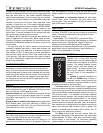
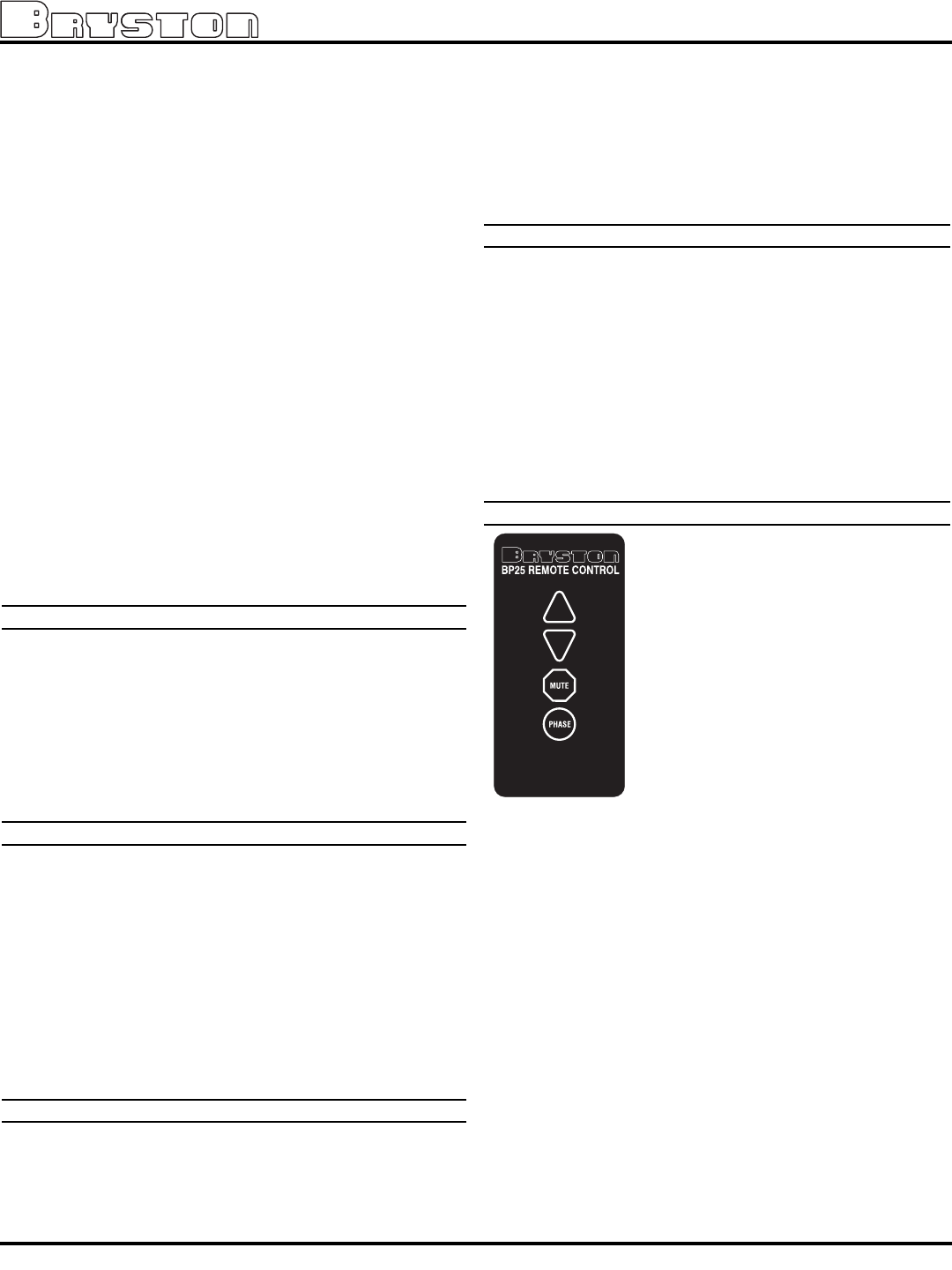
BP25 REMOTE CONTROL (Optional):
The Bryston model BP25 preamplifier is
supplied with a hand held infra-red
remote control unit (units without the IR
remote control are referred to as BP20
models). The remote features include
volume control, mute and polarity (or
signal phase). All remote control func-
tions may be operated manually from
the front panel of the preamplifier if
desired.
Volume is remotely controlled via
the UP and DOWN arrow buttons. A
motorized volume control ensures the
lowest distortion with maximum long term reliability. It is also
manually accessible on the front panel.
The Phase switch (or the “Polarity/Invert” toggle switch
on the front panel) allows you to reverse the absolute phase
of the audio signal (not to be confused with the left-versus-
right channel phase), because polarity reversal can occur in
the recording chain. It is desirable to maintain absolute
phase as originally played in the recording hall as that will
provide the most accurate representation of the original
wave front. This may be audible in some cases as a more
realistic rendition of musical transients when the preampli-
fiers maintain non-inverting polarity at the Main output for all
inputs when the pilot light (or status LED) is green. The
polarity is inverted when the status LED is yellow. The “To
Tape” outputs are always non-inverted.
The Mute control mutes the main outputs (both bal-
anced and unbalanced) of the preamplifier, but not the tape
outputs (labeled “To Tape”). Refer also to the Power Supply
section earlier in this manual for information regarding
remote amplifier control (on/off) via the mute switch.
BP20/25 PreAmplifiers
4