


BP20/25 PreAmplifiers
INTRODUCTION
Thank you for choosing a Bryston PreAmplifier. Bryston
welcomes any suggestions you may have, or comments
regarding the operation of your amplifier. We consider you,
our customer, to be Bryston’s most important resource, and
your opinion is very much appreciated.
SETUP:
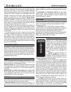
The Bryston BP-25 pre-amps, with remote-control, should
be placed where there is a direct line-of-sight between the
hand-held remote and the remote infra-red sensor eye
located on the left side of the pre-amplifier's front panel.
If you purchased the BP0/25P or BP20/25MC, which
includes a Phono section, avoid placing the preamplifier
directly on top of your power amplifier. Power amplifiers usu-
ally employ large power supplies and the transformer(s) in
the power supplies can cause interference (hum) with the
sensitive phono section inside the pre-amp.
Next, insert the 5-pin DIN cable from the outboard
power supply into the “Power Supply” input connector ( 5 pin
DIN) located on the rear of the preamplifier. Then plug the
power supply into an appropriate AC power outlet. The pre-
amplifier is powered up by engaging the push button switch
located on the front of the MPS-1 external power supply.
The "green" LED on the outboard power supply and the pre-
amplifier front panel indicates power-on.
EXTERNAL POWER SUPPLY (MPS-1) and REMOTE
TURN-ON FUNCTIONS:
The MPS-1 outboard power supply provides AC power for
the BP20 and BP25 preamplifiers. It has a push button
switch (push-to-set/push-to-release) located on the front
and a 2 colour LED to indicate power and mute status. This
LED mirrors the operation of the similar LED on the BP20/25
preamp (see the Visual Indicators section for more informa-
tion). On the rear of the unit there are two terminal blocks
and a two position slide switch.
The two position connector, or terminal block, accepts
bare wires between 12 and 26 AWG. Insulated wires should
be stripped to expose .3 inches (5/16” or 8mm) of bare wire.
This provides a means of turning on the MPS-1 power sup-
ply (and thus the BP20/25 pre-amp) remotely by connecting
a 4 to 12 volt (AC or DC) control signal. To enable remote
turn-on, the rear panel slide switch must be in the REMOTE
position and the front push-button power switch must be
depressed (activated).
To operate the MPS-1 power supply manually:
1st) Put the rear panel slide switch in the LOCAL position,
2nd) Press in the front panel push-button switch to turn on
the unit. Press in the push-button switch again to
release the switch and turn off the MPS-1 power sup
ply and the BP20/25 pre-amp.
The three-position connector provides a control voltage for
remote turn on/off of your Bryston amplifier(s) or other
amplifiers so equipped.
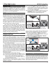
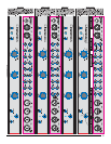
To turn on a Bryston amplifier by turning on the MPS-1:
1st) Connect the COM and +12V terminals of the three ter
minal connector on the rear panel of the MPS-1 to the
IN terminals on a Bryston power amplifier intended for
a 4~14V AC/DC control signal.
2nd) Put the amplifiers “EXTERNAL TURN ON” switch in the
EXTERNAL position for the amplifier to respond to
remote control turn-on signals (see figure 2).
To turn a Bryston power amplifier OFF and ON when the
BP20/25 pre-amp is MUTED and unMUTED respectively:
1st)Connect the +12V SW and COM terminals on the
back of the MPS-1 to the two IN terminals on the power
amp’s remote control connector.
2nd) Place the power amplifiers EXTERNAL TURN ON
switch in the EXTERNAL position.
CONNECTIONS to OTHER EQUIPMENT:
All inputs and outputs employ fully discrete active circuitry
and all input and output connectors have gold plated contact
surfaces. Only cables with high quality gold plated connec-
tors should be used with your pre-amp to avoid noise and
distortion from the corrosion that will eventually appear on
poorly plated cable connectors.
3
Figure 1: Turning “SST” power amps on & off via the MPS1 power supply
Figure 2: Turning “SST” power amps on & off via the BP20/25 MUTE switch