


Page 5
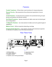
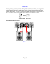
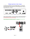
Rear panel description
1. AC fuse holder - Holds the AC Line fuse. This fuse is an 8 Amp / 250 Volt
Slow Blow fuse. Replace with same type and value fuse
only.
2. AC Input receptacle - For attaching the supplied AC power cord to the
amplifier.
3. Speaker outputs - For connecting the speakers to the amplifier. Explained
further on page 8.
4. Amplifier control muting input/output -
To provide remote switching of mute on/off of the amplifier.
Explained further on page 5.
5. Line level outputs - For connecting signal to another amplifier (daisy chaining).
6. RCA inputs - For connecting signal patch cables (interconnects) from the
preamplifier to the amplifier to pass signal.
7.Level controls - For adjusting the input level to the amplifier. Explained
further on page 6.
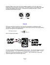
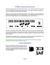
Control muting
A control is provided on each ST260 amplifier to allow remote switching of mute on/off.
The preamplifier’s control output, such as is provided with B&K series preamplifiers, can
be utilized to provide a control signal to the ST260. If more than one amplifier is being
controlled, the control signal can be extended to include each successive unit by simply
running an RCA type audio cable from the CTRL OUT connector of the first amplifier to
the CTRL IN connector of the next unit (commonly referred to as ‘daisy chaining’). An
example of how to connect two amplifiers is illustrated in figure B.
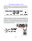
If a source other than a B&K series preamplifier is used to control multiple amplifiers,
only the control output voltage from the source is critical. It must be within the range, as
indicated on the rear panel, 5-24 volts DC is required. The amplifier will provide each
successive amplifier with a control voltage of 12 volts DC for reliable operation. The
amplifiers control output may be used as a source of 12 VDC @ 125 mA for other user
applications as well.
DO NOT POWER MOTORS WITH THIS CIRCUIT.