


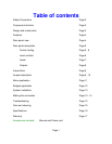
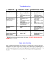
Page 9
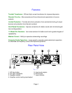
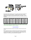
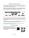
)LJXUH)
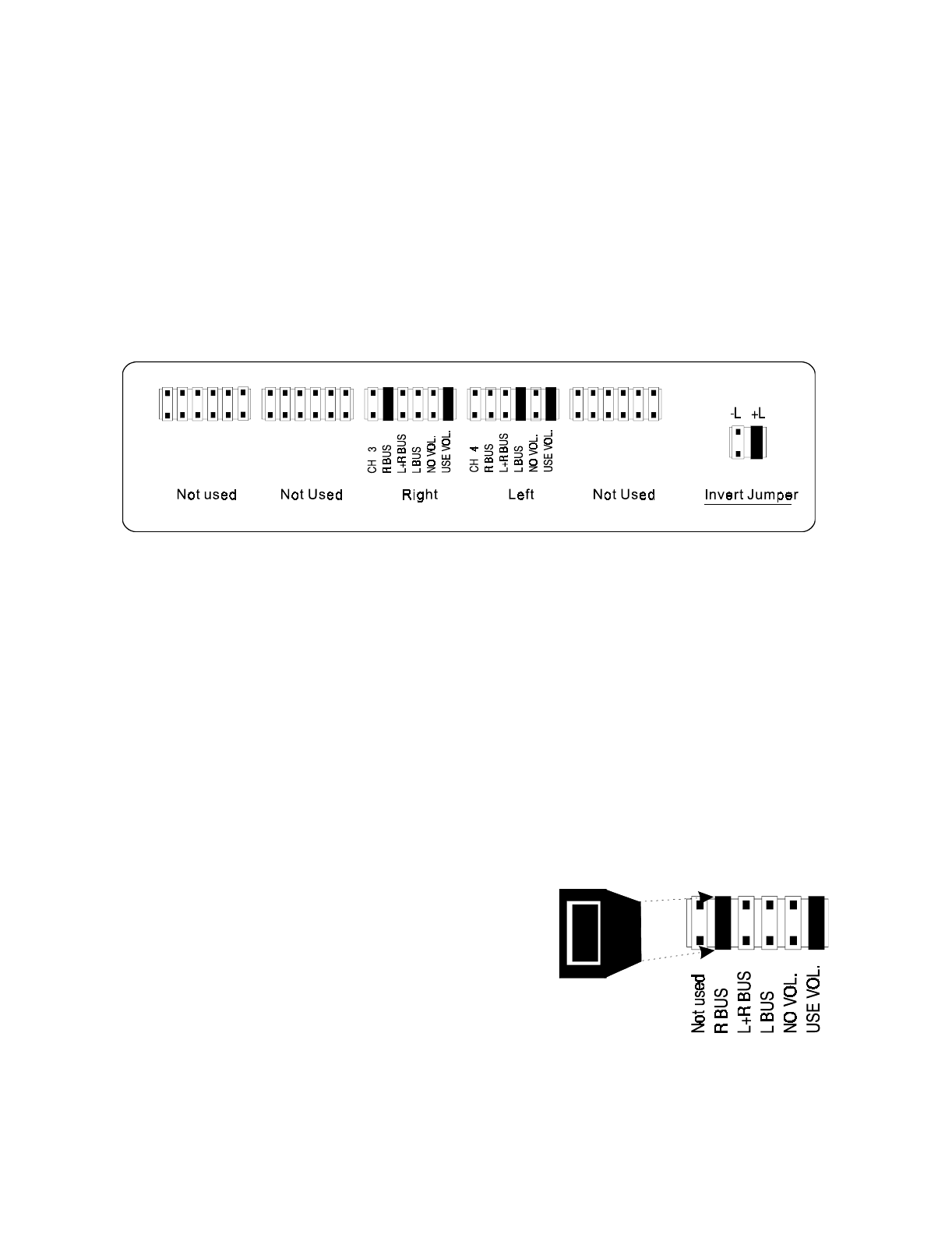
)LJXUH*
ST260’s internal bus structure
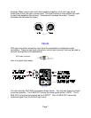
In order to
g
ain access to the internal bus structure,
y
ou must first remove the top cover.
Turn the amplifier so the rear panel is facin
g
y
our. The jumper modules ma
y
be seen
on the circuit board just behind the level controls.
Below is the default setup for the ST260 amplifier. B
y
arran
g
in
g
the jumpers allows
y
ou
to confi
g
ure the amplifier for different applications. If
y
ou wish to use the amplifier as a
stereo (two channel) amplifier,
y
ou need not chan
g
e an
y
of the settin
g
s.
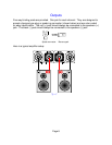
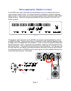
In order to reconfi
g
ure the ST260’s channels, remove the source control
g
roup jumper
from its present position (if necessar
y
) and install it on the terminal
y
ou wish to select as
the source for that channel. Make sure it has been inserted on both terminal pins of the
jumper modules.
To complete the confi
g
uration, the volume
g
roup jumper should be placed at either the
‘USE VOL’ or ‘NO VOL’ terminal dependin
g
on
y
ou confi
g
uration.
Note: A channel that is not bein
g
used in your confi
g
uration should have its jumper plu
g
s
installed at the default position as shown in Fi
g
ure F.
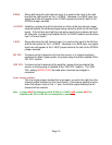
Jumper description
Fi
g
ure G illustrates the jumper modules used in
confi
g
urin
g
each channel. Each jumper terminal
location is convenientl
y
labeled as to the source it
can be confi
g
ured to provide. Explained further on
the followin
g
pa
g
e.