


13259 0303
11
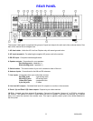
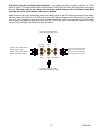
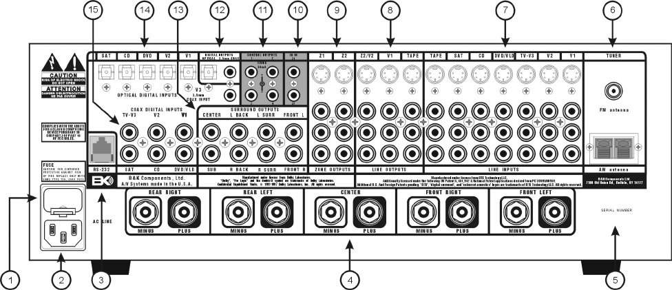
REAR PANEL
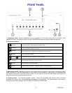
The receiver’s back panel is organized into groups of inputs and outputs for audio and video as shown below. See
back of this manual for an enlarged view.
1. AC fuse holder - Holds the AC Line fuse. Replace only with same type and value.
2. AC input receptacle - For attaching the supplied AC power cord to the receiver.
3. RS-232 input - Computer interface applications.
4. Speaker outputs - Connections for your speakers.
Red binding posts - speakers (+)
Black binding posts - speakers (-)
5. Serial number - The serial number of your unit is located on back of the unit.
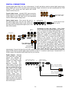
6. Antenna inputs - Connections for the AM and FM antennas.
7. Line inputs - Connections from your audio/video sources.
Red RCA jacks - right analog audio
White RCA jacks - left analog audio
Yellow RCA jacks - composite video
4 pin din jacks - S-video
8. Line level A/V outputs – Switched fixed level A/V outputs to an audio or video recorder.
9. Zone 1 (A) and Zone 2 (B) video outputs - Outputs to your video monitors.
10. IR in - Accepts input from external IR receptors. Connect an IR repeater (“home run”) to IR IN for controlling
the receiver. This method of control is useful when the front IR receptor is blocked (for example, by a cabinet
door) or to control the receiver from another room. This input is typically used in place of an emitter attached to
the front panel.