


8 ULTRAGRAPH PRO FBQ6200/FBQ3102/FBQ1502 User Manual
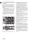
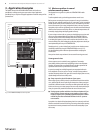
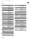
(18) The ULTRAGRAPH PRO FBQ6200 features a built-in limiter for each channel.
Use the LIMITER switch for its activation.
(19) (21)
(22)(20)(18)
(26) (25) (24)
(23)
Fig. 2.4: FBQ6200 control elements
(19) The limiter display informs you about the amount of gain reduction
perfomed by the limiter.
(20) The limiter connes the signal to an adjustable signal level. Use the
THRESHOLD control to adjust the threshold value of the limiter from -6to
+22 dB. When the control is in the “-6 dB” setting, the gain reduction is
very pronounced; the more you turn the control toward “+22 dB”, the gain
reduction is lower. When the threshold control is in its right-most position,
the limiter is not applied.
2.3.2 Noise generator
By using the built-in noise generator, you can create the so-called “pink noise”
that can be used to adjust your P.A. system to specic acoustic characteristics of
various venues.
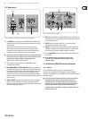
(21) Activate the pink noise generator by using the PINK NOISE switch.
Thebuilt-in switch illumination blinks red when the pink noise generator
isactivated.
(22) Read o the noise generator’s signal level on the LED display.
(23) Use the NOISE LEVEL control to adjust the volume of the pink noise
yougenerate.
Room resonance and sound transfer characteristics of the P.A. system cause some
frequencies to be more prominently present while other frequencies are less
present. Pink noise is a neutral signal that can be played back via the P.A. system
in order to measure these sound characteristics.
Such a measurement of the frequency response by using a special microphone
in conjunction with a real-time analyzer (a real-time analyzer is for example
integrated into the BEHRINGER ULTRACURVE PRO DEQ2496) delivers the basis
for setting up the equalizer. More pronounced frequencies are lowered,
andthose frequencies that are not so prominently featured are increased,
thusapproximately achieving linear reproduction.
◊ Try to orient yourself on a frequency whose signal level lies in the 0 dB
to -3 dB range in order to avoid overdriving the equipment connected
(e.g. power amplifier, crossover).
2.3.3 Subwoofer section
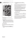
(24) The LED display indicates the signal level present at the SUB OUT connector.
(25) The signal level present at the subwoofer output connector can be adjusted
by using the LEVEL control.
(26) To activate the subwoofer output, please depress the SUBWOOFER switch.
In general, the location of a subwoofer is not critical, since the source of
deeper freqencies is not easily determined. However, to achieve optimal sound
resolution, you should try to position the subwoofer in a central location between
the two main speakers. This way, you minimize run-time dierences and the
sound quality deterioration associated with them.