


6 ULTRAGRAPH PRO FBQ6200/FBQ3102/FBQ1502 User Manual
2. Control Elements and Connectors
2.1 Front panel
In this chapter we will describe various control elements of your equalizer.
Allcontrols and connectors are explained in detail, and you will also nd useful
hints on how to best use them. Since the three equalizers in the FBQ series
are fairly similar, let’s start with the control elements of the FBQ1502 and
the FBQ3102 that are similar to the control elements found on the FBQ6200.
TheFBQ6200 additionally features extra control elements that will be explained
in detail later on.
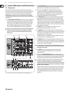
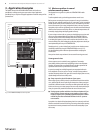
(1) The INPUT/OUTPUT LEVEL METER lets you keep an eye on the signal level
in order to avoid distortion. Depending on the position of the I/O METER
IN/OUT switch
(2), the display shows either the input or the output signal
(switchdepressed) level. When the signal level reaches roughly +18 dB,
thatis, 3dBbelow clipping starts to occur, the red CLIP LED lights up.
The level meter on the FBQ1502 displays only the output signal level.
◊ Attention: extreme frequency boosts in connec tion with a high input
signal level may lead to over driving your equipment. Should this
occur, it is necessary to reduce the input signal level by using the
INPUT control.
(4) (5)
(3)
(4)
(2) (1) (3)
(5) (6) (7)
(1)
(6)
(8) (9)
Fig. 2.1: Front panel control elements of the FBQ3102 (above) and of the FBQ1502 (below)
(2) The I/O METER IN/OUT switch lets you alternate between displaying the
input and the output signal level. When the switch is depressed, the output
signal level is shown. The FBQ1502 does not feature this switch.
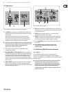
(3) When you press the FBQ switch, the FBQ feedback detection system
is activated. The frequency (or frequen cies) that evoke feedback is/are
indicated by means of a lighted fader LED. All other LEDs are toned down.
Now, simply lower the respective frequency range somewhat until you
eliminate the feedback and the LED no longer lights up.
(4) The AUDIO IN/OUT switch is used to enable or disable the entire equalizer
section. The FBQ1502 does this electronically, while the FBQ3102 and the
FBQ6200 feature a relay-driven hard bypass function. As long as the switch
is not depressed or while the equalizer is not powered up, the inputs and the
outputs are directly connected to one another. The AUDIO IN/OUT switch is
used to alternate between A and B, i.e. to compare the original unprocessed
signal with the processed signal.
(5) The INPUT control is used to adjust the input signal level. You can
boost/attenuate the signal level from +15 to -15 dB.
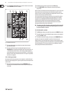
(6) The LOW CUT control is used to adjust the lower cut-o frequency of your
ULTRAGRAPH PRO. The high-pass lter (18 dB/oct.) covers the range between
10 and 400 Hz, whereby the lter lets the signal pass through unprocessed,
when the control is in the 10 Hz position.
The FBQ1502 features a switchable high-pass lter (LOW CUT) instead of a
low cut control, and its cut-o frequency is 25 Hz.
(7) The HIGH CUT control is used to adjust the upper cut-o frequency of your
ULTRAGRAPH PRO. The low-pass lter (18 dB/oct.) covers the range between
2.5 and 30 kHz, whereby the lter lets the signal pass through unprocessed
when the control is in the 30 kHz position.
◊ Use the high-pass and low-pass filters to define the frequency range
you wish to process. This provides you with an efficient way to limit the
bandwidth you work with.
(8) The RANGE switch lets you alternate between the maximum value
of lowering/increasing of individual frequencies from 12 dB to 6 dB
(switchdepressed).
(9) These are the 31 SLIDING CONTROLS (FBQ1502: 15 sliding controls per
channel) for individual frequency bands. When in “0” position, the particular
frequency range is not processed at all. To boost a frequency range, pull the
sliding control upward; to attenuate, pull the sliding control downward.
◊ To emphasize a frequency range, you don’t necessarily have to move
its respective sliding control upward; try lowering surrounding
frequency ranges instead. This way, you avoid causing the next piece of
equipment in your sound path to overdrive. You also preserve valuable
dynamic reserve (“headroom”).
Sliding controls feature LEDs that indicate the signal level of their particular
frequency ranges through their varying illumination intensity: what better
way to show critical frequencies that evoke feedback. How to best use
your ULTRAGRAPH PRO to detect these critical frequencies is described in
chapter3.2.1.