


11 ULTRAGRAPH PRO FBQ6200/FBQ3102/FBQ1502 User Manual
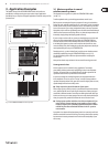
4. Installation
4.1 Rack mounting
The FBQ1502 requires one height unit (1 HU) for mounting in a 19" rack,
theFBQ3102 two height units, and the FBQ6200 three height units. Please allow
at least an additional 4" of space for the connectors on the back panel.
Be sure that there is enough space around the unit for cooling and please do
not place your ULTRAGRAPHPRO on high-temperature devices such as power
ampliers etc. to avoid overheating.
For rack mounting, please use M6 metal nuts and bolts.
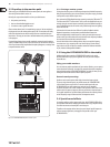
4.2 Audio connections
You will need many dierent cables for the various applications. The following
illustrations show how these cables should be laid out. Please use exclusively
high-grade cabels.
The ULTRAGRAPH PRO is installed with electronically servo-balanced inputs and
outputs to avoid hum noise problems.
You can, of course, also connect unbalanced devices to the balanced inputs/
outputs. Either use mono plugs, or connect the ring and sleeve of stereo plugs
(bridge pin 1 and pin 3 when using XLR connectors).
◊ Please ensure that only qualified personnel install and operate the
ULTRAGRAPH PRO. During installation and operation the user must
have sufficient electrical contact to earth. Electrostatic charges might
affect the operation of the unit.
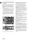
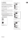
output
For unbalanced use, pin 1 and pin 3
have to be bridged
1 = ground/shield
2 = hot (+ve)
3 = cold (-ve)
input
12
3
1
2
3
Balanced use with XLR connectors
Fig. 4.1: XLR connectors
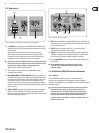
strain relief clamp
sleeve
tip
sleeve
(ground/shield)
Unbalanced ¼" TS connector
tip
(signal)
Fig. 4.2: ¼" TS connector
strain relief clamp
sleeve
ring
tip
sleeve
ground/shield
For connection of balanced and unbalanced plugs,
ring and sleeve have to be bridged at the stereo plug.
Balanced ¼" TRS connector
ring
cold (-ve)
tip
hot (+ve)
Fig. 4.3: ¼" TRS connector
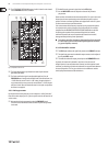
strain relief clamp
sleeve
ring
tip
sleeve
ground/shield
Connect the insert send with the input and the
insert return with the output of the eects device.
Insert send return ¼" TRS connector
ring
return (in)
tip
send (out)
Fig. 4.4: ¼" TRS connector for insert send/return applications