


7
EURORACK UB1204-PRO/UB1204FX-PRO
LEVEL
For level matching, the stereo inputs feature a LEVEL switch which
selects between +4 dBu and -10 dBV. At -10dBV (home-recording
level), the input is more sensitive than at +4 dBu (studio level).
2.2.2 Equalizer stereo channels
The equalizer of the stereo channels is, of course, stereo. The
filter characteristics and crossover frequencies are the same
as those of the mono channels. A stereo equalizer is always
preferable to two mono equalizers if frequency correction of a
stereo signal is needed. There is often a discrepancy between
the settings of the left and the right channels when using separate
equalizers.
2.2.3 Aux sends stereo channels
In principle, the aux sends of the stereo channels function in
just the same way as those of the mono channels. As aux send
paths are always mono, the signal on a stereo channel is first
summed to mono before it reaches the aux bus.
2.2.4 Routing switch, solo and channel fader
BAL
The function of the BAL(ANCE) control corresponds to the
PAN control in the mono channels.
The balance control determines the relative proportion between
the left and right input signals before both signals are routed to
the main stereo mix bus.
The MUTE/ALT 3-4 switch, the MUTE-LED, the PEAK-LED, the
SOLO switch and the channel fader function in the same way
as the mono channels.
2.3 Connector panel and main section
Whereas it was useful to trace the signal flow from top to
bottom in order to gain an understanding of the channel strips,
we now look at the mixing console from left to right. The signals
are, so to speak, collected from the same point on each of the
channel strips and then routed to the main section all together.
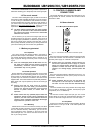
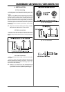
2.3.1 Aux sends 1 and 2
Fig. 2.6: AUX SEND controls of the main section
A channel signal is routed to aux send bus 1 if the AUX 1
control is turned up on the corresponding channel.
AUX SEND 1 (MON)
The AUX SEND control MON acts as master control for aux
send 1 and determines the level of the summed signal. In the
UB1204FX-PRO, the MON control is called AUX SEND 1.
AUX SEND 2 (FX)
Similarly, the FX control (AUX SEND 2) determines the level for
aux send 2.
SOLO
You can use the SOLO switch (UB1204FX-PRO only) to
separately monitor the aux sends via the CONTROL ROOM/
PHONES outputs and check these with the level meters.
+ If you want to monitor the signal of just one AUX
bus, none of the other SOLO SWITCHES should be
pressed and the MODE switch must be in the SOLO
position (not pressed down).
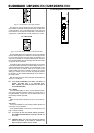
2.3.2 Aux send connectors 1 and 2
Fig. 2.7: Aux send connectors
AUX SEND 1
If you use aux send 1 pre-fader, you would usually connect
the AUX SEND 1 connector to monitors via a power amp (or an
active monitor system). If you use aux send 1 post-fader, proceed
as described under aux send 2.
AUX SEND 2
The AUX SEND 2 connector outputs the signal you picked up
from the individual channels using the FX control. You can connect
this to the input of an effects device in order to process the FX
bus signal. Once an effects mix is created, the processed signal
can then be routed from the effects device output back into the
STEREO AUX RETURN connectors.
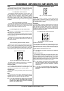
2.3.3 Stereo aux return connectors
Fig. 2.8: Stereo aux return connectors
STEREO AUX RETURN 1
The STEREO AUX RETURN 1 connectors generally serve as
the return path for the effects mix generated using the post-
fader aux send. This is where you connect the output signal of
the external effects device. If only the left connector is used, the
AUX RETURN automatically operates in mono.
+ You can also use these connectors as additional
line inputs.
STEREO AUX RETURN 2
The STEREO AUX RETURN 2 connectors serve as the return
path for the effects mix generated using the FX control. If these
connectors already function as additional inputs, you can route
the effects signal back into the console via a different channel,
with the added benefit that the channel EQ can be used to adjust
the frequency response of the effects return signal.
+ In this instance, the FX control of the channel being
used as an effects return should be turned fully
counterclockwise, otherwise feedback problems
could occur!
+ If you wish to use the internal effects processor,
no connectors should be plugged into STEREO AUX
RETURN 2.
2. CONTROL ELEMENTS AND CONNECTORS