


5
EURORACK UB1204-PRO/UB1204FX-PRO
The interface of BEHRINGER mixing consoles is optimized for
these tasks enabling you to easily keep track of the signal path.
1.2 The users manual
The users manual is designed to give you both an overview of
the controls, as well as detailed information on how to use them.
In order to help you understand the links between the controls,
we have arranged them in groups according to their function. If
you need to know more about specific issues, please visit our
website at http://www.behringer.com, where youll find
explanations of e.g. effects and dynamics applications.
+ The block diagram supplied with the mixing console
gives you an overview of the connections between
the inputs and outputs, as well as the associated
switches and controls.
For the moment, just try and trace the signal path from the
microphone input to the aux send 1 connector. Dont be put off
by the huge range of possibilities; its easier than you think! If you
look at the overview of the controls at the same time, youll be
able to quickly familiarize yourself with your mixing console and
youll soon be making the most of all its many possibilities.
1.3 Before you get started
1.3.1 Shipment
Your mixing console was carefully packed in the factory to
guarantee safe transport. Nevertheless, we recommend that
you carefully examine the packaging and its contents for any
signs of physical damage, which may have occurred during
transit.
+ If the unit is damaged, please do NOT return it to us,
but notify your dealer and the shipping company
immediately, otherwise claims for damage or
replacement may not be granted.
1.3.2 Initial operation
Be sure that there is enough space around the unit for cooling
purposes and to avoid over-heating please do not place your
mixing console on high-temperature devices such as radiators
or power amps. The console is connected to the mains via the
supplied cable. The console meets the required safety standards.
Blown fuses must only be replaced by fuses of the same type
and rating.
+ Please note that all units must be properly
grounded. For your own safety, you should never
remove any ground connectors from electrical
devices or power cables, or render them in-
operative.
+ Please ensure that only qualified people install and
operate the mixing console. During installation and
operation, the user must have sufficient electrical
contact to earth, otherwise electrostatic discharges
might affect the operation of the unit.
1.3.3 Warranty
Please take time to fill out and return the warranty card within
14 days after the date of purchase, so as to be entitled to benefit
from our extended warranty. Alternatively, you can use our
online registration option available on the world wide web
(www.behringer.com). You will find the serial number on the
rear of your mixing console.
2. CONTROL ELEMENTS AND
CONNECTORS
This chapter describes the various control elements of your
mixing console. All controls, switches and connectors will be
discussed in detail.
2.1 Mono channels
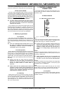
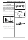
2.1.1 Microphone and line inputs
Fig. 2.1: Connectors and controls of mic/line inputs
MIC
Each mono input channel offers a balanced microphone input
via the XLR connector and also features a switchable +48 V
phantom power supply for condenser microphones.
+ Please mute your playback system before you
activate the phantom power supply to prevent
switch-on thumps being directed to your loud-
speakers. Please also note the instructions in
chapter 2.4.2 Voltage supply, phantom power and
fuse.
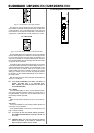
LINE IN
Each mono input also features a balanced line input on a 1/4"
connector. Unbalanced devices (mono jacks) can also be
connected to these inputs.
+ Please remember that you can only use either the
microphone or the line input of a channel at any
one time. You can never use both simultaneously!
LO CUT
The mono channels of the mixing consoles have a high-slope
LO CUT filter for eliminating unwanted, low-frequency signal
components (75 Hz, 18 dB/octave).
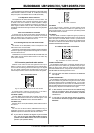
GAIN
Use the GAIN control to adjust the input gain. This control
should always be turned fully counterclockwise whenever you
connect or disconnect a signal source to one of the inputs.
2.1.2 Equalizer
All mono input channels include a 3-band equalizer. All bands
provide boost or cut of up to 15 dB. In the central position, the
equalizer is inactive.
2. CONTROL ELEMENTS AND CONNECTORS