


6 Documentation Number TCDA0997 Manual
B&B Electronics -- PO Box 1040 -- Ottawa, IL 61350
PH (815) 433-5100 -- FAX (815) 433-5104
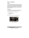
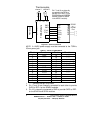
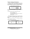
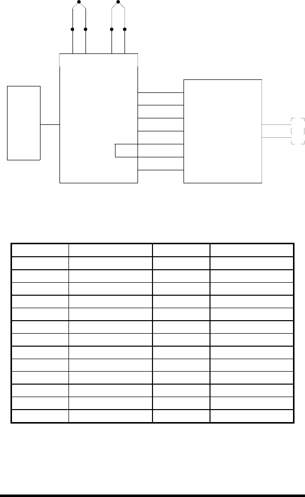
Figure 3.1: TCDA Connections
NOTE: A 12VDC power supply must be connected to the TCDA’s
2.5mm power jack.
1. ------- denotes that pin is not used.
2. Pin 17 and 18 are internally connected to each other to provide
5VDC to REF+ for the SDAXX modules.
3. Pin 19 is internally connected to GND to provide 0VDC to REF-
for the SDAXX and SPDA modules.
provide +5V to REF+ in the
modules (AGND to AGND
Pin 17 and 18 are internally
connected in the TCDA to
XXXSDAXX and XXXSPDA
A/D ch.
A/D ch.
in the ADIO12 module).
REF-
REF+
+5VDC
P
o
w
e
r
S
u
p
p
l
y
2
.
5
m
m
P
o
w
e
r
J
a
c
k
T
C
D
A
M
o
d
u
l
e
TC #1
19
GND
18
17
19
18
17
GND
7
TC #0
8
9
GND
1
GND
7
8
9
GND
1
Thermocouples
y
e
l
l
o
w
r
e
d
T1-T1+
channel 1
r
e
d
y
e
l
l
o
w
T2-T2+
channel 2
A
/
D
M
o
d
u
l
e
RS-485
Port
RS-232
or
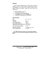
Table 3.1: Pinout of TCDA Module
Pin # Function Pin # Function
1 GND 14 -------
2 ------- 15 -------
3 ------- 16 -------
4 ------- 17 looped to pin 18
5 ------- 18 looped to pin 17
6 ------- 19 GND
7 GND 20 -------
8 TC # 0 21 -------
9 TC # 1 22 -------
10 ------- 23 -------
11 ------- 24 -------
12 ------- 25 -------
13 -------