


Documentation Number TCDA0997 Manual 5
B&B Electronics -- PO Box 1040 -- Ottawa, IL 61350
PH (815) 433-5100 -- FAX (815) 433-5104
Chapter 3: Connections
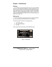
Overview
This chapter will discuss the connections required to operate the
TCDA thermocouple amplifier. Connections between the A/D
converter and the TCDA should be kept as short as possible.
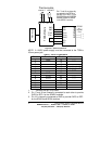
Thermocouple Connections
The TCDA can amplify voltage from a K-type thermocouple.
Only one thermocouple can be connected to each channel. The
thermocouple connections are made using terminal blocks. The
positive (+) lead of the thermocouple must be connected to T1+ and
the negative (-) lead to T1- (T2+ and T2- for channel 2). Make sure
that both leads of the thermocouple are connected to the same
channel. Color coding is used to designate the thermocouple’s
polarity. A K-type thermocouple’s negative lead is red, and the
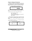
positive lead is yellow. Figure 3.1 shows the thermocouple
connections.
Power Supply Connections
A 2.5mm power jack is provided on the side of the TCDA hood.
A 12VDC power supply must be connected to the 2.5mm power
jack. The 232PS is recommended (not included).
Output Connections
The amplified voltage of the thermocouple is available through a
male DB-25P connector. This connector is pin compatible with B&B
Electronics’ ADIO12 and SDAXX line of data acquisition modules.
The FBDA can also be used with the SPDA data acquisition
modules. The pinout of the TCDA is shown if Table 3.1. Figure 3.1
shows the connections required for the TCDA module.