8 Documentation Number FBDA0797 Manual
B&B Electronics -- PO Box 1040 -- Ottawa, IL 61350
PH (815) 433-5100 -- FAX (815) 433-5105
Sensors that incorporate bridge circuitry usually have
noticeable zero offsets. This should be considered when taking
measurements and determining gain. The easiest way to solve this
problem is to calibrate the system while avoiding zero inputs, and
correct for the zero offset in software.
Example:
If a 10lb. load cell needs to be calibrated, the suggested method
is the following:
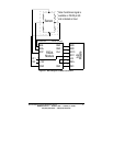
1. Make all of the required connections.
2. Place a 1lb. mass on the load cell. Record the voltage on DB-
25 pin 8 as Vouta. Pin 8 is A/D 0 on the SDAXX modules.
3. Add a second 1lb. mass onto the load cell. Record the voltage
on DB-25 pin 8 as Voutb.
4. Subtract Vouta form Voutb. The difference is the voltage, Vout,
which corresponds to 1lb.
5. Calculate what ((SIG+) - (SIG-)) is for 1lb. This is the voltage
produced by the sensor.
6. Use the Gain Equation to calculate the exact gain of the
amplifier.
7. Adjust P1, and repeat process until the desired gain is achieved.
8. Subtract Vouta from Vout. The difference is the zero offset
error. The zero offset error should be included in any equation
conversion equation used in your software.
Gain Equation
GAIN = Vout / ((SIG+) - (SIG-))


