


4 Documentation Number FBDA0797 Manual
B&B Electronics -- PO Box 1040 -- Ottawa, IL 61350
PH (815) 433-5100 -- FAX (815) 433-5105
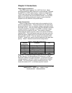
Data Acquisition Connections
The connections to the Data Acquisition Module are made
through a DB-25 (male) connector. The FBDA is pin compatible with
B&B Electronics’ SDAXX, and ADIO12 modules. This allows you to
simply plug the FBDA into one of the above data acquisition
modules, and the data acquisition module connections to the FBDA
are complete. Table 2.2 contains the DB-25 (male) pin
assignments.
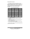
1. ------- denotes no connection.
2. The conditioned sensor signal is available on pin #8 and is
labeled Vout.
3. Pin #9 is connected straight through to terminal block A/D 1 (no
signal conditioning circuitry).
4. Pins #17 and #18 are looped to each other to provide +5V to
REF+ in the SDAXX line of A/D modules.
5. Pin #19 provides 0V to REF- in the SDAXX line of A/D modules.
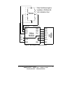
Figure 2.1 contains a diagram of the connections required to read
the signal produced by a sensor.
Table 2.2: DB-25 (Male) Pin Assignments
DB-25 Pin # Function DB-25 Pin # Function
1 GND 14 -------
2 ------- 15 -------
3 ------- 16 -------
4 ------- 17 looped to 18
5 ------- 18 looped to 17
6 ------- 19 GND
7 GND 20 -------
8 Vout 21 -------
9 A/D 1 22 -------
10 ------- 23 -------
11 ------- 24 -------
12 ------- 25 -------
13 -------