


Documentation Number FBDA0797 Manual 7
B&B Electronics -- PO Box 1040 -- Ottawa, IL 61350
PH (815) 433-5100 -- FAX (815) 433-5105
Chapter 3: Gain Selection
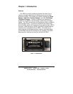
The FBDA has several different gain settings to provide the
largest possible voltage range for an A/D converter. The gain of the
FBDA is selected using a jumper, 6 jumper pins (labeled 1-6), and a
potentiometer (labeled P1). The FBDA is calibrated at the factory to
have a gain of 80 ± 2. To change the gain of the FBDA the
following steps should be followed:
1. Remove the cover from the FBDA using a small slotted
screwdriver.
2. There are six jumper pins labeled 1-6. Place the jumper on the
two pins selected from Table 3.1 below. Placing the jumper on
the two selected pins will set a gain near the values listed in
Table 3.1.
3. Make all of the required connections (power supply, A/D
converter, sensor, and excitation voltage), and turn on the
power.
4. Set up your sensor to provide a known input signal for the
FBDA. If you are using a load cell, place a known weight on the
load cell. This will produce a known input signal.
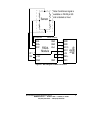
5. The output voltage from the FBDA can be read from DB-25 pin 8
(A/D 0 on B&B Electronics’ SDAXX data acquisition modules).
6. Adjust P1 to trim the gain to an exact value. The gain equation
is shown below. ((SIG+) - (SIG-)) is the input signal.
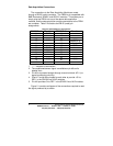
1. The potentiometer (P1) becomes more critical as the gain is
increased.
2. The gain range of 220 to 1000 is entirely decided by P1. When
P1 is turned completely in counter-clock-wise, the Gain will be
close to 220. When P1 is turned completely clock-wise, the
Gain will be greater than 1000.
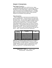
Table 3.1: Jumper Selection to Choose Gain
Gain Jumper Selection
25 Jumper pin 5 to pin 6
40 Jumper pin 4 to pin 5
80 Jumper pin 2 to pin 3
220-1000 Jumper pin 1 to pin 2