


4
ENGLISH
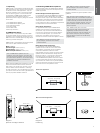
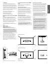
Diagram 3
Cable connection
4. Installing CWM3 Series Speakers
To install a CWM3 Series speaker, proceed as
described in the following paragraphs:
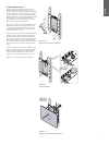
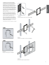
4.1 Using the supplied aperture template, mark a
cut line on the wall. Check the cut line denes the
correct aperture dimensions. Cut along the line with
an appropriate tool to create a rectangular aperture
in the wall.
Note: Ensure that there is enough free space
internally adjacent to the aperture for the dog
clamps.
Note: To reduce the possibility of the wall buzzing
or rattling, adhesive mastic can be applied
between the studs and sheetrock in the vicinity
of the speaker aperture.
4.2 If speaker cable is already present in the wall,
feed the cable through the aperture. If speaker
cables are not already installed, this should be done
at this stage. It is likely that you will need to gain
access through the oor above to route the cables
down through the wall space.
Leave enough spare cable through the aperture to
ease connection to the speaker, but not so much
that it is likely to buzz or rattle when pushed back
into the wall space. Approximately 1.0m (3 ft) is
appropriate.
Note: Always use high quality, low resistance
speaker cable. Low resistance is especially
important if the length of cable from amplier
to speaker exceeds 5m. Your local Bowers &
Wilkins retailer will be able to offer advice on
speaker cable selection if required.
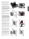
4.3 Now connect the speaker cable to the spring
terminals on the crossover board. Ensure that the
speaker connection polarity is correct: the cable
connected to the positive terminal on the amplier
should be connected to the red spring terminal
on the speaker. Similarly, the cable connected
to the negative terminal on the amplier should
be connected to the black spring terminal on the
speaker. Diagram 3 illustrates cable connection.
Note: If an amplier is already connected to the
cable it should be switched off while connections
are being made to the back box.
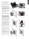
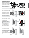
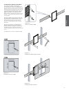
4.4 With the speaker connected to the cable, it
can be inserted into the wall aperture. Ensure that
the four dog clamps are rotated inwards so that
they can pass through the aperture, and then hold
the speaker ange ush to the wall. Take care that
the connection cable does not become trapped
anywhere.
To secure the speaker use a Phillips screwdriver
inserted through the dog-clamp access holes in the
front of the speaker. Take great care not to damage
the speaker drive units with the screwdriver. Engage
the screwdriver with each dog-clamp screw in turn
and tighten them. Diagram 4 illustrates inserting and
securing the speaker.
Note: If the wall is to be painted after the
speakers have been installed, the supplied paint
mask should be used.
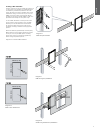
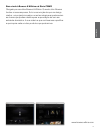
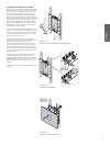
4.5 The grille can now be tted. The grille is held in
place magnetically so simply needs to be aligned
with the groove in the frame ange where it will click
into place. Diagram 5 illustrates tting the grille.
The CWM3 Series speaker is now installed and
ready for use.
Diagram 4
Secure the speaker
Diagram 5
Fitting the grille