


3
ENGLISH
1. Unpacking
CWM3 Series in-wall speakers are designed to offer
easy installation and high quality audio reproduction
for discrete custom install applications. They are
particularly suitable for use in humid environments
such as swimming pools. This manual describes
the installation of CWM3 Series speakers within
conventional stud and sheetrock (joist and
plasterboard) walls. It begins by listing the contents
of the carton:
1. Two CWM3 Series speakers
2. Two CWM3 Series speaker grilles
3. Two aperture templates
4. Two paint masks
5. Quick Start Guide
6. Warranty information
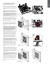
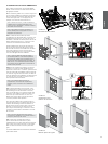
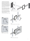
2. CWM3 Series Basics
CWM3 Series in-wall speakers comprise a bafe
carrying the speaker drivers, crossover circuit and
connectors, and a magnetically secured grille. The
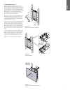
bafe is secured in the wall aperture by dog-clamps
that swing outwards and tighten.
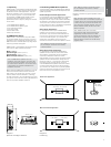
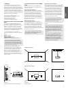
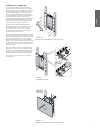
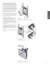
CWM3 Series in-wall speakers require wall aperture
and minimum depth clearance as follows:
Model CWM362
Aperture Height 275mm (10.9 in)
Aperture Width 181mm (7.2 in)
Minimum Depth Clearance 76mm (3 in)
Note: If CWM3 Series speakers are to be
installed in “new build” projects, pre-mount kits
and back boxes are available. Use of pre-mount
kits is described in Section 5. Use of back-boxes
is described in the separate CI300 Back-box
Installation document.
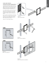
Before installing CWM3 Series speakers you should
ensure that the wall locations chosen are free of
obstructions such as pipe work, ducting or wiring
that will interfere with the installation. In existing
dry-wall construction, use a stud-nding tool to help
you map the wall construction and a pipe detector to
scan the proposed installation locations.
3. Positioning CWM3 Series Speakers
The appropriate position for CWM3 Series speakers
within the listening environment will depend on their
specic application:
General Background Audio Applications:
For applications where single CWM3 Series speakers
are required to operate independently to provide
background audio, they can be located substantially
as installation convenience and architecture dictate.
The only acoustic constraint to bear in mind is that
corner locations will result in signicantly emphasised
low frequencies and should be avoided.
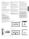
Stereo Audio Applications:
For applications where a pair of CWM3 Series
speakers is to be used for conventional stereo
reproduction, they should be located between 3m
(10 ft) and 5m (16.5ft) apart and a similar distance
in front of the listening area. Try to avoid corner
locations for the speakers and to ensure that
acoustic environment around each speaker is similar.
Note: Different acoustic environments might
be, for example, a bare wall and a heavily
curtained window.
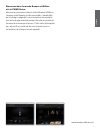
Multi-channel Audio Applications
For applications where multiple CWM3 Series
speakers are to be used for multi-channel audio
visual systems, the left and right front speakers
should be located either side of the screen
approximately 0.5m (20 in) away. The centre channel
speaker should be located either directly above or
below the screen or, in the case of an acoustically
transparent screen, directly behind. Surround
channel CWM3 Series speakers should be located
just behind and either side of the listening position.
Try to avoid corner locations for any of the speakers
and to ensure that the acoustic environment around
each front and surround speaker is similar.
Note: Different acoustic environments might
be, for example, a bare wall and a heavily
curtained window.
Diagram 2 illustrates the general speaker location
guidelines.
Note: The nature of the installation of in-wall
speakers means that it is sometimes impractical
to locate them in the acoustically ideal positions.
In these cases they should be located as close
as is practical to the ideal positions. Your local
Bowers & Wilkins retailer will be able to offer
advice if required.
Note: CWM3 Series drive units create
stray magnetic elds. We recommend that
magnetically sensitive items such as CRT
screens and magnetic cards for example, are
kept at least 0.5m (20 in) from the speaker.
LCD and plasma screens are not affected by
magnetic elds.
0.5m (20 in) 0.5m (20 in)
0.5m (20 in)
0.5m (20 in)
3m (10 ft) - 5m (16.5ft)3m (10 ft) - 5m (16.5ft)
3m (10 ft) -
5m (16.5ft)
Diagram 2
Positioning
Diagram 1
Aperture and height clearance
3m (10 ft) - 5m (16.5 ft)
0.5m (20in)0.5m (20in)
0.5m (20in)0.5m (20in)
3m (10 ft) -
5m (16.5 ft)
181mm (7.2in)
275mm (10.9in)
76mm (3in)
Stereo Audio Applications
Multi-channel Audio Applications