


6
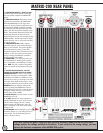
MATRIX-200 REAR PANEL
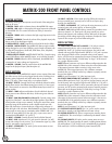
1. LOUDSPEAKER OUTPUTS – RIGHT and LEFT:
Connect to right and left speakers accordingly.
Use only speakers supplied with MATRIX-200
System.
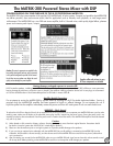
2. SUBWOOFER OUTPUT: XLR output to connect
optional active subwoofer to the MATRIX-200.
While the MATRIX-200 is a full range active
system, the very low frequency performance can
be enhanced by adding an external subwoofer.
The subwoofer will both extend the range of the
system, and add increased low frequency output
ability. The subwoofer XLR output jack has both
left and right channels combined, minus the
higher frequencies sent to, and reproduced by the
satellite speakers. The XLR output only has signal
pr
esent when the “sub sw” (sub switch; item # 3)
is in the on position.
3. SUBWOOFER ON/OFF: Used to activate
subwoofer output (2), and to activate high pass
filters on main channels. This improves perform-
ance of the system by causing a more ideal
acoustical summation of the subwoofer and main
speakers. It does so by limiting cone excursion,
and by increasing the headroom available to
both the speakers and amplifier.
4. HEADPHONES: 1/4” stereo jack used to con-
nect headphones for monitoring when speaker
use is not possible, or if headphones are prefer-
able.
NOTE: This jack is inactive if the speaker
cables are inserted into the speaker output jacks
(1).
5. VOLTAGE SELECTOR SWITCH: DO NOT
CHANGE THIS SETTING WITH THE AC MAINS
POWER ATTACHED!
This switch is only used to
modify the unit when it is transported to a differ-
ent location with a different available AC mains
source (such as moving a unit bought in the USA
to Europe). Please check that this switch is in the
appr
opriate position for your local electric source.
W
ARNING:
Using an impr
oper setting on this
switch can destr
oy the MA
TRIX-200, cr
eate an
electrical hazard and void your warranty! Do not
change this setting unless you must to match to
the AC mains power available.
6. POWER ON/OFF: Pr
ess this switch to tur
n the
MATRIX-200 on or off.
7. AC INLET: Male IEC AC mains connector for
standar
d detachable AC mains cor
ds. This cor
d
will also need to change if the unit is moved
between regions with different AC mains volt-
ages. It will require an AC mains switch setting
change as well.
8. FUSE HOLDER: This fuse depends on your local
AC Mains voltage. For 115V setting, this fuse is
a 5amp T5AL. For the 230V setting, the fuse
used is a T2.5AL as shown.
CAUTION: Connect the power cable only after you have absolutely made sure that the local mains
voltage matches the voltage specified on the device. If you connect to the wrong voltage, you may
destr
oy the electr
onic components of the MA
TRIX-200 system.