


9
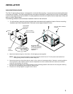
USE OF CONTROLS
1 1
1 1
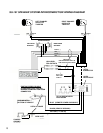
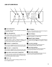
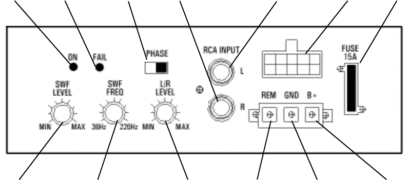
1 ON LED INDICATOR
This indicator lights green when the system is powered up
and operating normally.
2 2
2 2
2 FAIL LED INDICATOR
This indicator lights red when a system failure occurs
activating the overvoltage protection circuit.
3 3
3 3
3 PHASE SELECT SWITCH
This slide switch is used to change the phase of the
reproduced sound output from the SU-101 Speakers to
match the phase of the audio receiver system.
44
44
4 RCA INPUT - R CONNECTOR
This connector accepts the right channel low level output
RCA connector (LINE OUT) from the vehicle radio receiver.
5 5
5 5
5 RCA INPUT - L CONNECTOR
This connector accepts the left channel low level output
RCA connector (LINE OUT) from the vehicle radio receiver.
66
66
6 HIGH LEVEL INPUT/OUTPUT CONNECTOR
This 10-pin connector provides audio (speaker) connec-
tions between the sub-woofer enclosure, the satellite tweet-
ers and existing audio receiver system.
7 7
7 7
7 FUSE - 15A
This fuse provides surge/overvoltage protection for the
SU-101 speaker system.
12 34 5 6
7
8
9
1011
12
13
88
88
8 B+ TERMINAL
Connect +12 Vdc vehicle power to this terminal using the
Yellow wire supplied (4 meters long).
99
99
9
GND TERMINAL
Connect this terminal to vehicle chassis ground using the
Black wire supplied (1.3 meters long).
blbl
blbl
bl REMOTE (REM) TERMINAL
Connect the remote output from the car audio system to
this terminal using the Blue wire supplied (3 meters
long).
bm bm
bm bm
bm L/R LEVEL CONTROL
This control varies the audio output level to the
satellite tweeters between MIN and MAX.
bn bn
bn bn
bn SWF FREQ CONTROL
This control adjusts the sub-woofer low-pass-filter
cutoff frequency between 36 Hz and 220 Hz.
bn bn
bn bn
bn SWF LEVEL CONTROL
This control varies the audio output level to the sub-
woofer enclosure between MIN and MAX.