


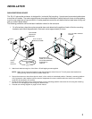

WIRING INSTRUCTIONS
The power connections for the SU-101 enclosure are made via a screw- tightened terminal block. Simply loosen the screw
fully insert the wire or spade lug under the respective terminal screw, then tighten the screw to secure the lug.
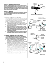
1. Power Connection
The battery terminal (B+) must be connected directly to the positive terminal of the vehicle battery to provide an
adequate voltage source and minimize noise. Connecting the battery terminal lead to any other point (such as the fuse
block) will not power-up the SU-101. Use only the Yellow wire supplied for this purpose. Connect this lead to the
battery terminal after all other wiring is completed.
2. Ground Connection
The ground terminal (GND) terminal connection is also critical for correct operation of the SU-101. Use only the
supplied Black wire with spade lugs for this purpose, and connect it between the ground terminal (GND) of the
enclosure and a metal part of the vehicle close to the mounting location. This wire should be as short as possible
and any paint or rust at the grounding point should be scraped away to provide a clean metal surface to which the
end of the ground wire can be screwed or bolted.
3. Remote Turn-On Connection
The SU-101 is turned on by applying +12 volts to the remote turn-on terminal (REM). The supplied Blue wire with
spade lugs should be attached between this terminal and the "Auto-Antenna" lead from the car stereo which will
provide +12 volts only when the car stereo is turned on. If the car stereo does not provide an Auto-Antenna lead,
the remote turn-on lead may be wired to an "Accessory" or "Radio" terminal in the car's fuse block. This will turn
the amplifier on and off with the ignition key, regardless of whether the car stereo is on or off.
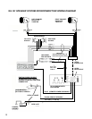
4. Speaker Connections
Wire the satellite speakers to the "Speaker Output" terminals as per the Output Wiring Diagram using the supplied
input/output extension cable assemblies. When mating the wiring to the speakers, pay careful attention to the
polarity of the speaker leads, and make certain they correspond to the polarity of the corresponding terminals on
the highlevel input/output 10-pin adapter harness. DO NOT ground any speaker leads to the chassis of the
vehicle.
5. Input Connections
The sub-woofer enclosure features both high and low-level input capability. Use either the low-level or high-level
inputs, not both. If low-level outputs are provided from the car stereo, it is recommended that the low-level inputs
be used for lowest distortion and best performance. Use good quality shielded audio cables with RCA plugs (not
supplied) at both ends to connect the stereo to the sub-woofer enclosure L and R low-level input jacks; keep the
cable lengths to a minimum to avoid noise.
If the car stereo does not provide low-level outputs, the sub-woofer may be connected via the speaker (high-level)
outputs from the stereo. Wire the speaker leads from the car stereo to the supplied 10-pin adapter harness
using the supplied RCA tip-jack cable assemblies as shown in the diagram (shielded cable is not required
for this application), and plug the harness connector into the mating High-Level Input connector on the enclosure.
Carefully mate and insulate all wire connections.
CAUTION: Use either the low-level or the high-level inputs on the enclosure. DO NOT use both input levels at
the same time.
7