


98
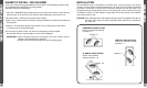
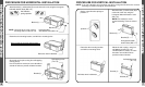
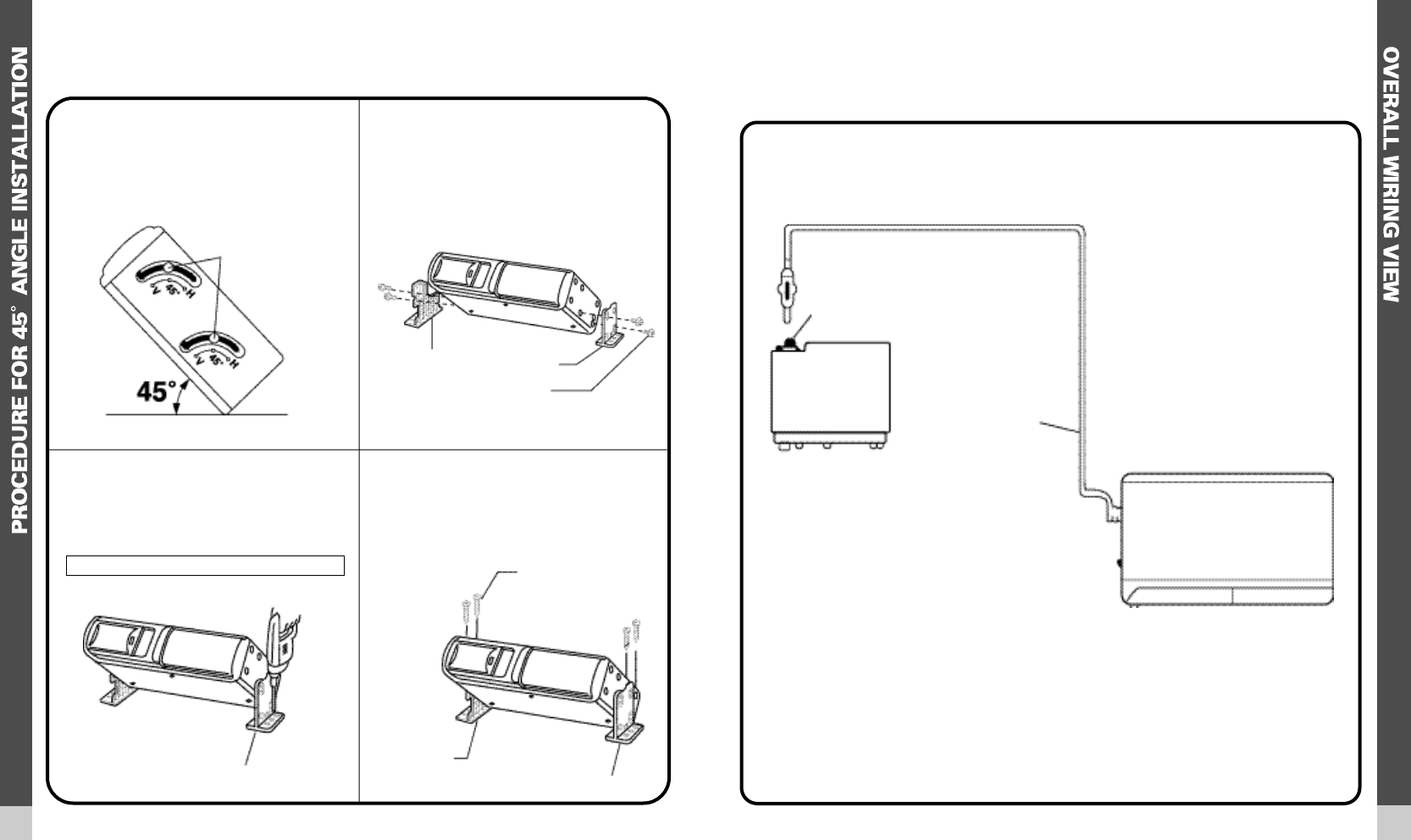
PROCEDURE FOR 45 ANGLE INSTALLATION
N O T E : If the anti-vibration spring position has been changed and verified for 45 a n g l e
mounting (as shown on page 6), start with step 2.
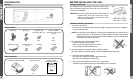
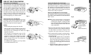
OVERALL WIRING VIEW
This page is provided to give you a quick look at the entire wiring of the ACC56M. Use it to
plan your wire routing paths and possible connection points. Detailed wiring is explained in
the following pages.
Set the 4 anti-vibration springs to
position “45°”
Determine the mounting location,and
drill four mounting holes.
Attach bracket (L) and bracket (R) to
each side of the unit,using the
hexagonal bolts with washer base
(M5 x 10).
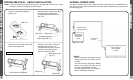
Mount the unit in place, using four
self-tapping screws (T5 x 12).
Use RTV(silicone sealer) on screw
threads or around the holes to
prevent moisture intrusion.
Bracket (L)
Bracket (R)
Bracket (L)
Bracket (R)
Hexagonal bolt with
washer base (M5 x 10)
Drill holes 4mm in diameter.
Self-tapping screw
(T5 x 12)
position 4 5
DATA CABLE
(15 FEET)
EXISTING RADIO
ANTENNA SOCKET
10-DISC COMPACT
DISC CHANGER
ACC56M
Never mount the unit near the fuel tank.
AQUATRONICS
OR VOYAGER
CDC READY
RADIO
NOTES:
When routing wires and cables from the
changer to the radio, it is best to conceal
the wires.
It may be necessary to press the RESET
button on the face of the radio the first
time after the ACC56M is lnstalled.
This will causethe radio to “recognize”
that the ACC56M is connected.